This thread has been locked.

If you have a related question, please click the "Ask a related question" button in the top right corner. The newly created question will be automatically linked to this question.

LMH6642: ADC to LPC4357

Part Number: LMH6642
Other Parts Discussed in Thread: LM7705, OPA365

Hi All

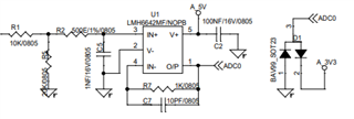
I am using LPC4357 series in my project. For the ADC part, I am using LMH6642. In this , ADC is showing some offset errors frequently. This offset varies with different boards. Some boards are working fine too. The 0-3.3V analog signal is given to LMH6642MF and the output  is directly connected to MC. While checking voltage at the output of LMH6642, its showing correct value. But the digital value read by MC has some offset. In some board its working fine too. MC is changed a couple of times and the LMH6642 also changed and tried. In some board its working , so I am not doubting on software or MC.

Recently I made a new board and tested.  It was giving exact values for ADC without any offset. But after two days, the same board started giving offset error. Still the voltage showing at the output of LMH6642 is correct. Without any ADC input, LMH6642 was giving around 20mV at the output. But ADC read by micro controller has an offset of 0.3V. After removing the power supply to LMH6642, the 0.3V offset was gone and the ADC gave 0V.

What could be the problem

  • Hello Mahesh,

      Is your setup the LMH6642 to the ADC to the MC? Would you be able to share a schematic?

      So what you are seeing is the offset at the output of the LMH6642 varies from near 0V (input offset voltage of LMH6642 is max +/-5mV) to 300mV (0.3V) on the same board at different measurements between a few days. Is this a continuous shift or are these spikes over time? If possible, can you also provide the measurement shots between good measurement vs bad measurement.

    Thank you,
    Sima

  • Hi Sima,

    Please find the above circuit. I have taken this section from an old design as it is. Since I dont need very high precision ADC, I didnt study much on this circuit.

    The signal ADC0 mentioned in the schematics is directly connected to the ADC pin of MC.

    Actually, in the latest board I checked, 3 days back it was giving a digital value of 2 for no input ( 10 bit ADC gives digital value of 1023 for 3.3V and 0 for 0V as per the design )

    But now it started giving a digital value around 150 ( equivalent analog voltage is 0.5, in previous message I mentioned it as 0.3V by mistake )  

    But in both the cases, the voltage observed by multimeter is around 20mV only. The voltage observed at AMP output using multimeter is correct. But MC is reading an offset error. 

    is there any problem at this interface 

    Thank you,

    Mahesh

  • Hello Mahesh,

       Thank you for the additional explanation. Unfortunately, I won't be able to assist with the LPC4357. 

       I don't see any issue with the circuit, but you are limiting the bandwidth quite a bit. What is your input signal characteristics (amplitude, bandwidth, any DC offset since this amp is set as a single supply)? But, there really shouldn't be a settling issue when interfacing this amplifier with 10-bit ADC internal to MC at 400ksps. 

       When you apply an input now are you seeing the same amount of offset at other voltage levels? So, for example for a 0.5V, are you obtaining a digital value of 300? But, that is very strange it changed over a course of a few days. There weren't any additional changes on the board between the two different checks? 

    Thank you,
    Sima 

  • Hi Mahesh,

    the problem is that no rail to rail OPAmp can properly work when the output voltage is near the supply rails. It's true that the output voltage can come the supply voltage rails very close, within 100mV or even closer without strong load. But this is only for DC or low frequency signals. It's not valid for higher frequency signals because the OPAmp is no longer working in linear operation but goes into saturation.

    To see where the OPAmp is still working in linear operation you will need to have a look at the "Large Signal Gain" specification which is given for the LMH6642 for an output voltage between 0.5V to 4.5V for a 2k load. This means that the dynamic performance of OPAmp is only guaranteed when the output voltage stays 0.5V away from the supply rails. Ok, for a high ohmic input resistance of your ADC you can surely come closer to the supply rails a bit. But keep in mind that the ADC with its sampling input switchings presents a dynamic load to the OPAmp. And I'm pretty much sure that at an output voltage of 20mV or even 0V the LMH6642 is no longer working properly.

    There are simple remedies: Avoid going all the way down to 0V at the output of LMH6642 by biasing the input with an offset voltage of some hundreds of millivolts. Or power the LMH6642 at its negative supply voltage pin with the LM7705. This chip provides an output voltage of -0.23V without needing an extra supply voltage. This very clever LM7705 was designed for exact this case.

    You might ask how the sampling result of ADC can give 300mV while the output of LMH6642 shows 20mV all the time? Because what you see at the output of LMH6642 with a multimeter is an averaged DC value.

    Three other points I want to focus on:

    1. Allthough my phase stability analysis has shown that your circuit is stable, I would never run such a fast chip without isolation resistor at its output. So I would insert a 100R resistor (or so) between the output of LMH6642 and the BAV99 clamp protection circuit. This has the additional advantage that the current through the protection diodes and by this the voltage drop across the BAV99 gets limited.

    2. Point 1 directs me to another possible cause of malfunction. I just saw that the absolute maximum ratings of ADC say that the input voltage must not exceed the analog supply voltage, which is 3.3V in your case. But the LMH6642 is powered by 5V and can easily destroy the ADC input when emitting 5V (during power-up or power-down, for instance !), even with the BAV99 clamp. This would explain why everything is working normal at the begin but starts to behave weird after a few days. So you should better take an OPAmp buffer which is also supplied by 3.3V.

    3. The LMH6642 shows a very high input bias current which causes a considerable voltage drop across R1//R5. So you should better take a modern TI's CMOS OPAmp running at 3.3V supply voltage. Without searching the OPA365 immediately comes into my mind.

    Kai

  • Hi Sima and Kai,

    That was very useful and I will try to implement the same changes in the design. The information was useful to understand the root cause for the issue. I will try to work out on it and will get back to you if any assistance is required.

    Thank you very much for your valuable response and information.

    Regards,

    Mahesh P M

  • Hello Mahesh and Kai,

      Thank you Kai for the detailed explanation and suggestions! 

      I hope the redesign fixes the issue. I will be closing the thread, but feel free to come back and reply to this thread for further questions or updates.

    Thank you,

    Sima