This thread has been locked.

If you have a related question, please click the "Ask a related question" button in the top right corner. The newly created question will be automatically linked to this question.

INA826EVM: Output slowly decays to 0V

Part Number: INA826EVM
Other Parts Discussed in Thread: INA826

Hi Team,

Our customer encountered an issue while using the INA826EVM. According to our customer.

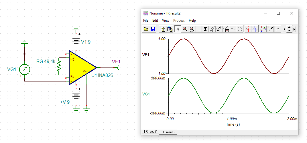
I have an INA826EVM evaluation board, I am powering the board with a +-9V source, I have R5 connected to GND, there is a 0-20k variable pot across the gain input I have adjusted to output a 2x gain.  I am inserting a 1000 hz 1v p-p signal into the input, and the output signal looks correct for about 5 seconds and slowly decays to 0V, if I cycle the power it repeats the same problem, I can vary the input, I have placed .1uF caps on the filter inputs, nothing seems to correct the issue.

Not sure what I am doing wrong. Just need assistance on what the issue would be. I have a second board that was doing the same problem and a third board that is working normally.

Not working, only added C1,C3,R5 as 0 ohm, 20k pot

Not working removed c1,c3, added 0 ohm R5, 20k RG pot
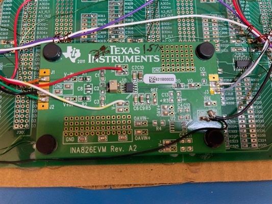
Working as expected

Regards,

Danilo

  • Hi Danilo,

    I think this has to do with the input bias currents of INA826. They need a path to signal ground as discussed in section 8.3.6 of datasheet.

    This circuit should work:

    danilo_ina826.TSC

    Kai

  • Hi Danilo,

    Kai's explanation makes sense. I think that the input is missing bias current path to GND as well. Please try his suggestion. 

    If you have any additional questions, please let us know. 

    Best,

    Raymond

  • Hi Kai and Raymond,

    Thank you very much for your help.

    Regards,

    Danilo

  • Hi Kai and Raymond,

    We have received this feedback from our customer.

    I did try the 47k bias resistors to GND and did not work with dual voltage, I tied -Ve to GND and that did not work so I tried single supply method with 5V v+ and tied -v to GND and looks like it will work, I just have to add an offset DC voltage to output. Still would like to understand why the split voltage supply is not working.

    Regards,

    Danilo

  • Hi Danilo,

    the customer should not add these 47k resistors but should connect the -input of INA826 to signal ground as I did. And he should not have any other connection between the input signal and the INA826 board. The original input signal (as long as not being connected to the board) should freely float.

    Kai

  • Hi Danilo,

    Please try Kai's approach or the following configuration. I do not see other issues in the setup. 

    If you have additional questions, please let us know. 

    Best,

    Raymond

  • Hi Danilo,

    I am going to close this inquiry. 

    If you have additional questions, please let us know. 

    Best,

    Raymond

  • Hi Kai and Raymond,

    I have updated our customer but I didn't received any feedback. It seems that the solution provided by Kai resolved the issue. 

    Thank you very much for your help.

    Regards,

    Danilo