Other Parts Discussed in Thread: JFE150, LMH6629, TINA-TI
It seems to me that the JFE2140 provides similar or better characteristics than the 2SK389-A or LSK389-A.
Therefore can substitute (not pin to pin) the last two for better results?
Thanks!
This thread has been locked.
If you have a related question, please click the "Ask a related question" button in the top right corner. The newly created question will be automatically linked to this question.
Hi Neo,
the JFE2140 seems to be better in many parameters. But the 10Hz noise voltage densitiy at 2mA looks worse compared to the LSK389 (2.4nV/SQRT(Hz) versus 1.5nV/SQRT(Hz)). I hope this is a typo?
Also, the JFE2140 doesn't specify maximum noise voltage densities. The LSK389 does. For many users this will be a severe disadvantage.
Kai
Hello Neo,
I will do a comparison of the devices you mentioned and get back to you on Monday once I have reviewed.
Best Regards,
Chris Featherstone
Neo,
Spec per spec the JFE2140 will provide better results in the most applications. Although the JFE2140 has slightly higher 1/f noise at 10Hz, it has half the input capacitance relative to the LSK389. LSK389 is 25pF and JFE2140 is 13pF at 5V. Below we provide the Input Capacitance vs VDS voltage. The input capacitance will play a role in bandwidth as well as signal attenuation from the sensor in certain applications. Lower input capacitance is favorable. There is a trade off between noise and input capacitance. The larger the JFET the lower the noise with the penalty being higher input capacitance. The JFE2140 strikes a great balance here.
It is important to note that the broadband noise is overall better. For audio applications the frequency bandwidth of concern will be 25Hz-20kHz. In this region the overall noise is favorable to the JFE2140.

Best Regards,
Chris Featherstone
Hi Enrico,
yes, the LSK489 has a lower input capacitance than the LSK389 but also more noise.
All these JFETs are state-of-the-art and only differ in the subtle tuning between input capacitance and noise. As Chris already mentioned, the larger the JFET the higher the input capacitance and the lower the noise and vice versa.
Ultra low input capacitance is necessary, for instance, in EEG amplifier input stages to achieve a sufficient common mode rejection in combination with the highly varying contact resistances which can often be seen in such an application. Ultra low input capacitance JFETs showing ultra low noise can help to avoid costly and component consuming cascode designs then. Another effect that can demand for a JFET with ultra low input capacitance in some applications is the generation of distortion resulting from input capacitance modulation.
Kai
Hello Kai, thank you very much indeed.
I saw on Mouser that InterFET offers many ultra low capacity types but the noise is over 8nV/√Hz at 10 Hz and they cost over € 30. However at the moment InterFET doesn't have an equivalent model with a low Ciss and noise like the LSK489 (1.8nV/√Hz and 4pF), and TI JFE2140 it doesn't help me much either with 2.4nV/√Hz and 13 pF.
With products on the market as of this date, which dual JFets would you personally choose for audio use?
Enrico,
I am personally building a pre-amp with the JFE2140. 10Hz doesn't matter in audio applications since it is outside of the human audible range. Even in production while mixing ultra low end gets filtered out purposely by the mix engineer because it eats up headroom in the final mix. This headroom loss doesn't allow the final song to achieve its perceived loudness level in comparison to professionally mastered music if it remains in the mix. Ultimately to have flexibility you can record down to 25Hz. The human audible range starts at 20Hz however this can vary up from 20Hz. 10Hz noise isn't audible.
In my opinion the JFE2140 offers a great balance for audio with its ultra low noise in the audio frequency range and low input capacitance.
Best Regards,
Chris Featherstone
Hi Enrico,
I aggree with Chris. The increased noise at 10Hz should not bother you. The human ear is extremely insensitive to the lowest audio frequencies. This nice link might interest you:
http://www.sengpielaudio.com/calculator-dba-spl.htm
Professional audio recordings heavily suppress the very lowest audio frequencies, because the unhearable contents of music can make power amplifiers consume huge power and clip. Even the voice coil of woofer can leave the region of maximum excursion and can become damaged.
What JFET is best for you depends a bit on your actual circuit. But the BB's JFE2140 is known to offer an optimum compromise between noise and input capacitance.
Kai
Dear Chris and Kai, thank you very much for your comments.
Regarding the use of low noise, low Ciss dual JFets in preamps, in one application note of the LSK489, Engineer Bob Cordell says: "examination of the LSK389’s specification shows an input capacitance of over 20 pF. This will cause intermodulation distortion as the circuit’s input signal increases in frequency if the source impedance is high.
This is because the JFET junction capacitances are nonlinear [...] The LSK489 has much lower input capacitance of only 4 pF means that it will maintain its high input impedance as the frequency of the input signal rises. More importantly, using the lower-capacitance LSK489 will create a circuit that is much less susceptible to intermodulation distortion than one using the LSK389".
Chris and Kai, I completely agree with you regarding the noise at 10Hz, I don't pay attention to it. Instead it's the Ciss value that I take into consideration, as Cordell says above, the higher it is, the more the input signal degrades.
With the use of datasheets I have obtained a table with the lowest capacitance and noise parameters of dual JFets currently available on the market:
|
||||||||||||||||||||||||||
To start the study of a MM preamp from scratch, I am tempted to choose the SMPU430 due to its low value of Ciss (4 pF) but the JFE2140 is way more convenient, it costs eight times less...
Kind regards,
Enrico Borsetti
Enrico,
Bob is correct on the input capacitance and distortion. The broadband noise is more of the concern in my opinion. The SMPU430 may have lower input capacitance but probably has higher broadband noise in the audio spectrum. This is the main trade off to look at. Noise vs distortion. Nice table by the way!
Best Regards,
Chris Featherstone
Hello again,
Thanks for the quick reply and the advice to observe the broadband noise.
Erno Borbely in his article "JFets: The New Frontier", he promoted the Cascode configuration to reduce the Ciss. Chris what do you think? Would the cascode help JFE2140's broadband and Ciss? Your time permitting, with the equipment available at TI laboratories, in a near future could you verify it with your instruments and share the Cascode results with us?
Thank you very much for your kind collaboration.
Regards,
Enrico
Enrico,
We can make the measurement. Please allow a couple weeks. We will put it in our queue.
Best Regards,
Chris Featherstone
Hi Chris, that's great news!
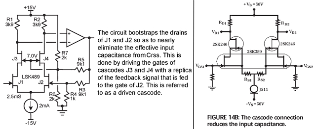
Regarding the Cascode circuitry to reduce Ciss, in the left image Bob Cordell makes an all JFet configuration, as does Erno Borbely in the image 14B at right. They say to avoid BJT's because they introduce "shot noise".
Chris, what is your opinion on this? How much do the transistors degrade the signal?
Enrico,
Due to the larger magnitude and nature of the bias current (Ib) in a bipolar device, shot noise is present. If we look at relative magnitudes of bias current into the base of a bipolar vs the bias current into the gate of a FET, we can observe an order/s of magnitude difference between the two, µA's vs femto to pico amps.
Forward bias diodes exhibit shot noise by the charge over coming the a potential barrier, this includes shot noise due to the collector current in a BJT.
Shot noise is a function of base current:

All that to say that, yes there is shot noise present in BJT devices and one could avoid this by the configurations presented. BJTs have advantages over FETs with higher transconductance and output impedance therefore providing higher intrinsic gain with the aforementioned tradeoffs being larger Ib and shot noise.
Best Regards,
Chris Featherstone
Enrico,
I have some other tradeoffs to consider that I discuss in my application report that can be found here:
I forgot to mention that the shot noise in audio circuits will be present as a pop such as popping popcorn. The degree to which this can be heard however will come down to the design decisions made and the signal to noise ratio. If you provide plenty of gain prior to the BJT stage one could design a circuit such that the shot noise is not audible. Poor design decisions that degrade the signal to noise ratio will have the opposite affect and could lead to shot noise becoming audible.
Best Regards,
Chris Featherstone
Hi Enrico,
I'll join in on this thread here -
Thanks for this info, I have seen the article by Bob Cordell but not Erno Borbely. One thing I'd like to add is that "cascoding" alone (I think "cascoding" is very general) does not lower the CISS, it has to be used in a configuration similar to above. The key with these circuits is that this cascode configuration forces a constant VGD across the input JFET, effectively removing the CRSS (or, CGD) capacitance. I do think this comes at the expense of the overall improvement in output impedance that cascoding offers, but that may be negligible depending on the configuration.
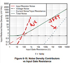
Regarding shot noise, this is the noise associated with the flow of current into the base of a BJT, and generally is the dominant factor in "current noise" in op-amps. The impact this has is when large source resistances are used (i.e. sensors with very high output impedance). The current noise converts to voltage noise with higher impedances, so, it will definitely cause noise problems with high-impedance circuits. This is the main advantage to JFETs and why they are commonly used.
The JFE2140 has a graph showing the total noise vs. "Input Gate Resistance" - note the current noise*input resistance is never a dominant factor in the JFET. If you were to create a similar graph with a common bjt, the "current noise*input resistance" would dominate after 1kOhm to 10 kOhm resistance, leading to much higher total noise.
I attempted a drawing below to help explain:
Let me know if this helps.
Regards,
Mike
Hi Enrico,
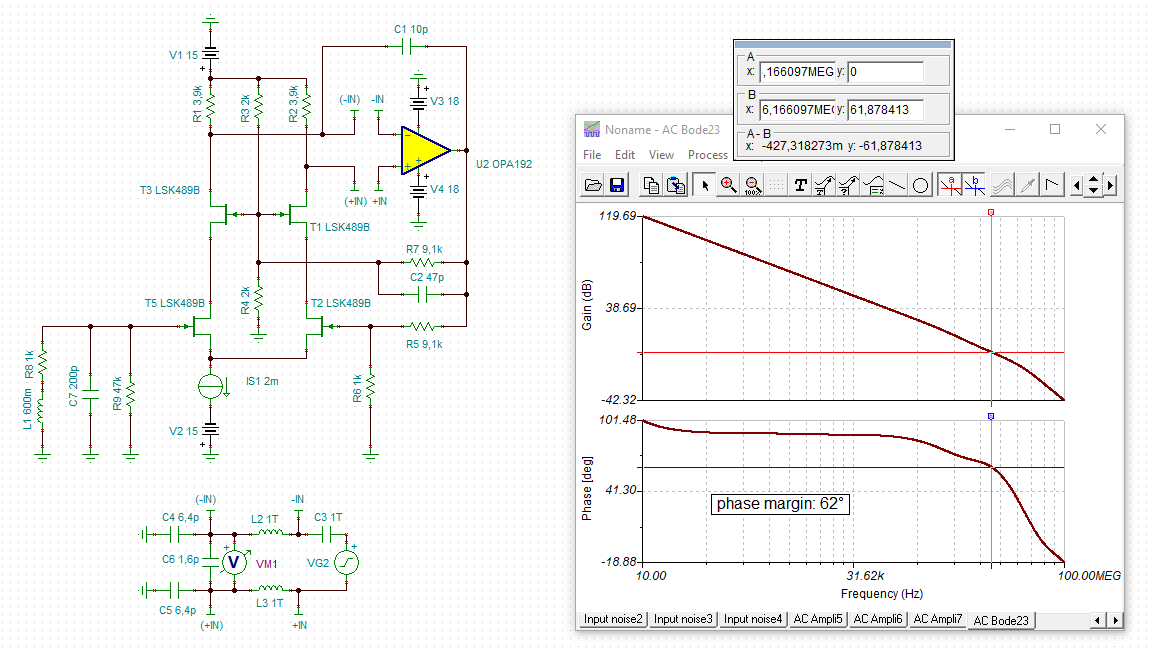
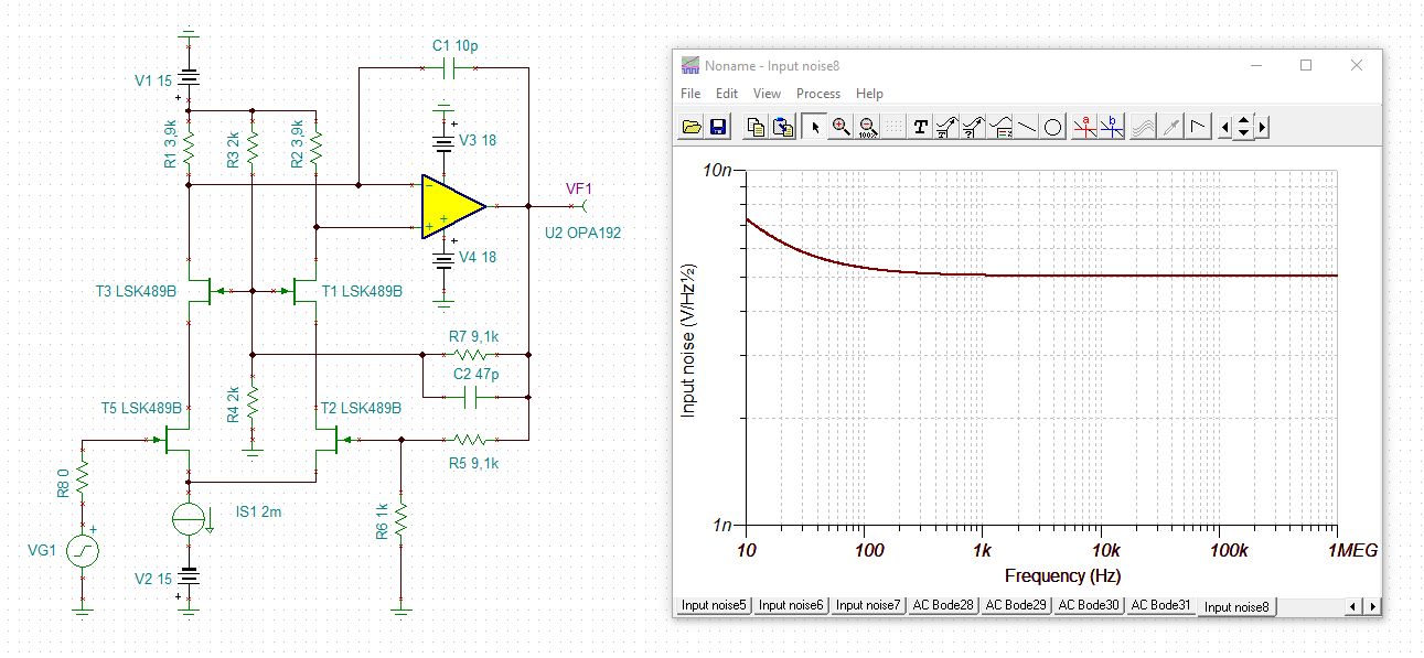
here are some simus I originally made for an EEG amplifier. I have modified them for moving magnet amplification. You can easily put the JFE2140 into the simu:
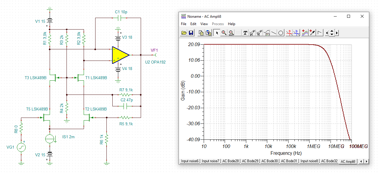
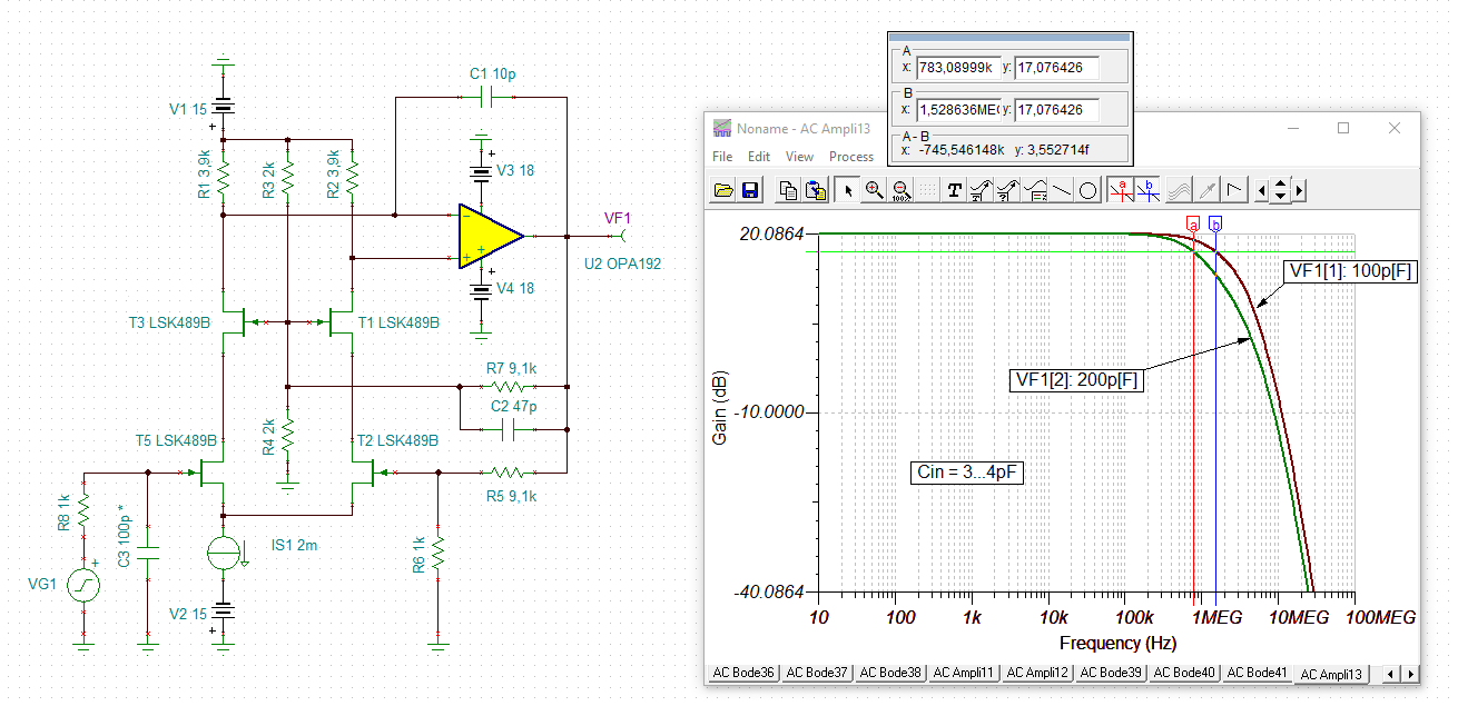
Kai
Thank you very much Chris for your valuable information and also for the link to the "JFE150 Ultra-Low-Noise Pre-Amp" application, excellent.
Welcome to the thread, Mike! Thanks to you too for the BJT versus JFet chart and additional information. Borbely's article can be found here: www.interfet.com/.../audio-electronics-jfet-new-frontier1-2.pdf
Regarding the various types of noise that exist, time ago I got a headache from reading Douglas Self's book "Small Signal Audio Design". There are dozens and dozens of pages on this topic.
Chris, a question: to my knowledge, it has not yet been produced by TI, AD, LT and other companies, an operational amplifier dedicated to audio use consisting 100% by JFets. There are several little jewels like the LMH6629, EL2125, LT1028, etc. which have internally Transistors and JFets but they aren't entirely made by JFet.
What is this due to?
What are the limitations for making such "All JFet" audio op amp?
I have never found an article that explained why.
Looking forward,
Enrico
Dear Kai, excellent!
Thanks very much for your schematics and simulations. I have Proteus 8.13 but I haven't been able to simulate a circuit with LSK489 + JFE2140 yet because the two Spice models haven't been added to the library at this date (and I don't know if they will ever add them...).
What component do you use (IS 1) for 2mA current sinking? Borbely in his schematic (1990s) uses the Vishay J511 which is now obsolete, Mouser and others don't have it in their catalog anymore.
Guys, , I am amazed by your fantastic and prompt collaboration! Thanks a lot to you all.
- Enrico
Enrico,
Good question. We do have our JFET front devices such as the OPA164x family. I'm going to discuss with my design team tomorrow regarding your question.
Best Regards,
Chris Featherstone
Hi Enrico,
as the input signal of a MM pick-up is very small (a few mV) compared to the +/-15V supply voltages, you can easily replace the current source by a simple resistor. In my simulations a 8k04 resistor would do. The simulations do not show any negative impact when using a simple resistor instead of a current source, provided the input signal is very small, of course.
The advantage of JFETs is said that they do not show the nasty popcorn noise some BJTs sometimes suffer from. Having said this, there some OPAmps having JFETs at the inputs which nevertheless can show popcorn noise. It is said that this noise would come from the constant current source in the input stage being formed by BJTs.
As you do not plan mass production, I assume, you could easily hand select the BJTs, or course, and only take BJTs being as free as possible from popcorn noise and other noise.
Kai
Thanks a lot Kai for your message. I wonder if the 8k04 resistor has a counterproductive impact on the amplification of the small signal since for this value, at the frequency of 1000 Hz, the RMS noise is 0.359791 uV and the Noise Level is -128.879 dBv (calculations performed with the online "Thermal Noise Calculator"). Perhaps for this reason Borbely avoided the resistor and put the J511 in its place. The downside is that a current regulator diode equivalent to the J511 costs 7 Euros!
Cheers,
Enrico
Hi Enrico,
the simus don't show any relevant change:
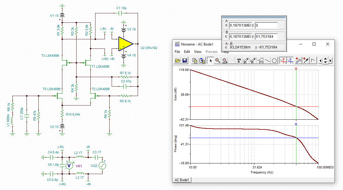

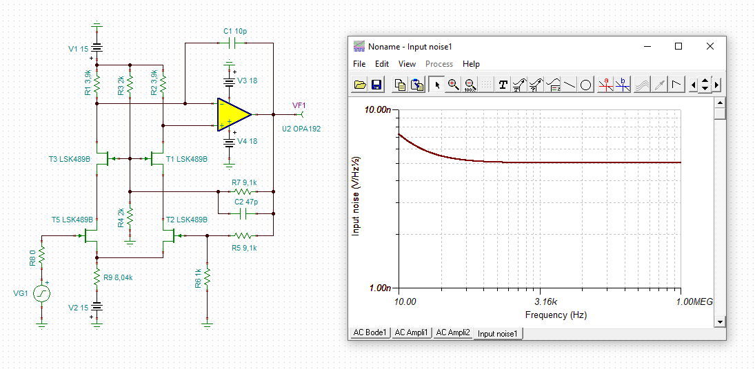
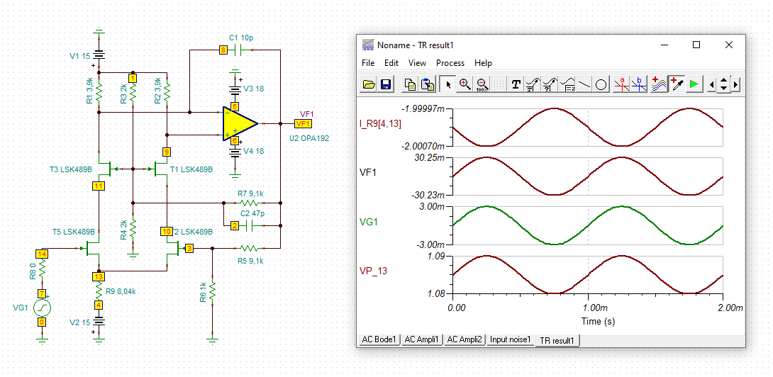
The only disadvantage, if at all, could be that due to the manufacturing tolerances of JFETs the resistor would have to be calibrated for each circuit for 2mA current flow. But in your case this would not play any role, right?
Don't understand me wrong, if the input signal would be much greater, a simple resistor instead of a current source would no longer do the trick as well as shown above.
Kai
Enrico,
We have a training PDF created by some of my Burr Brown mentors and colleagues. This document covers some trade offs between bipolar, CMOS and JFET amplifiers.
https://training.ti.com/sites/default/files/docs/Op%20Amp%20Tech%20Overview_0.pdf
There is a nice summary between different topologies at the end. One thing to note is that JFETs require a negative Vgs in order to modulate the drain to source channel and thus the Ids current. This is one challenge in designing subsequent stages post input stage when a BJT can serve just as well or better with more ease in the design. By better I mean that the BJT stages can provide higher gain. The JFETs offer a unique combination of high input impedance and low noise and are fantastic for input stages and boosting the signal up to get a high SNR prior to using the bipolar stages in a design. There are many tradeoffs to consider.
Here is another application report one of our senior engineers wrote discussing tradeoffs between input stage topologies.
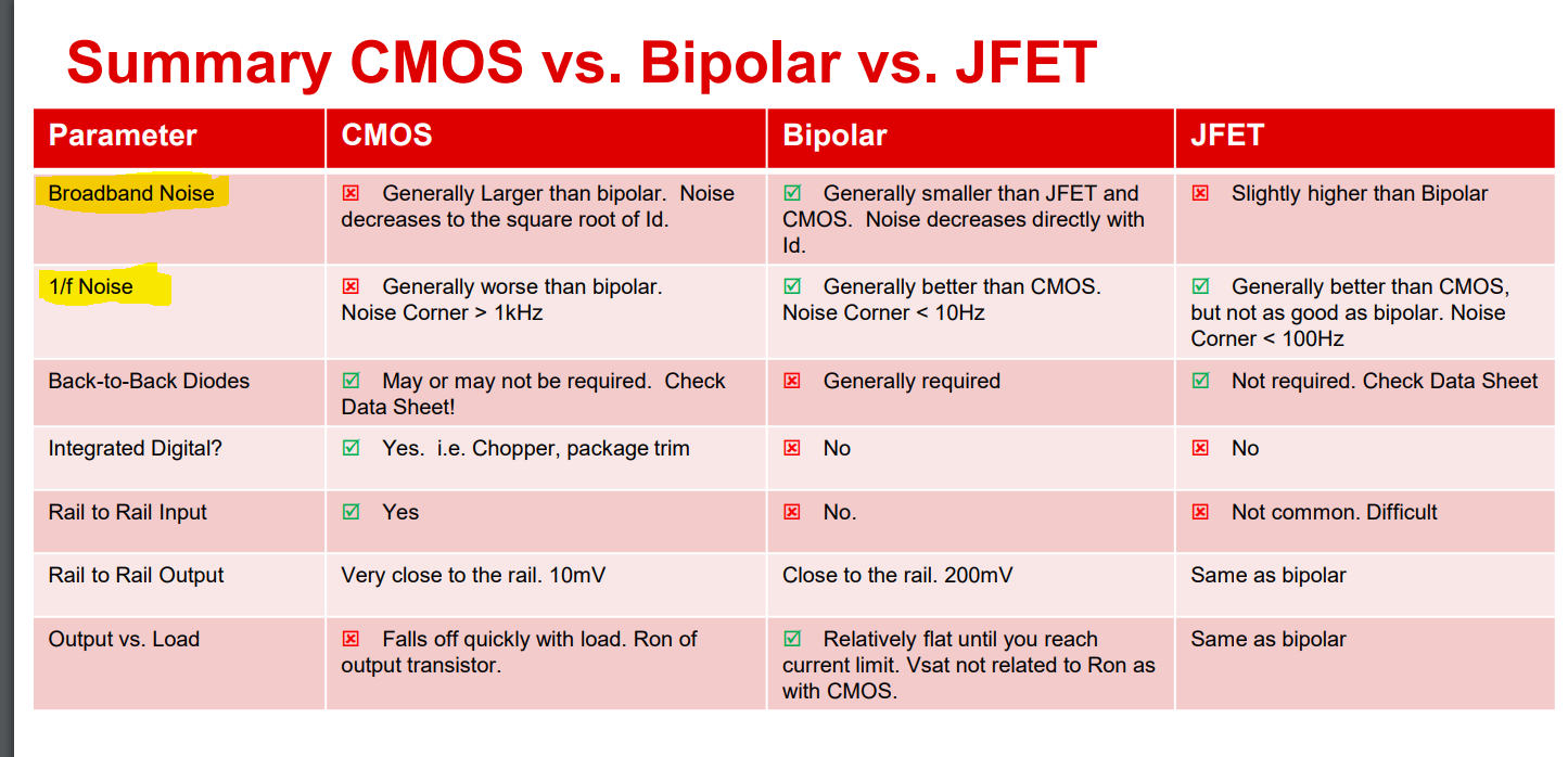
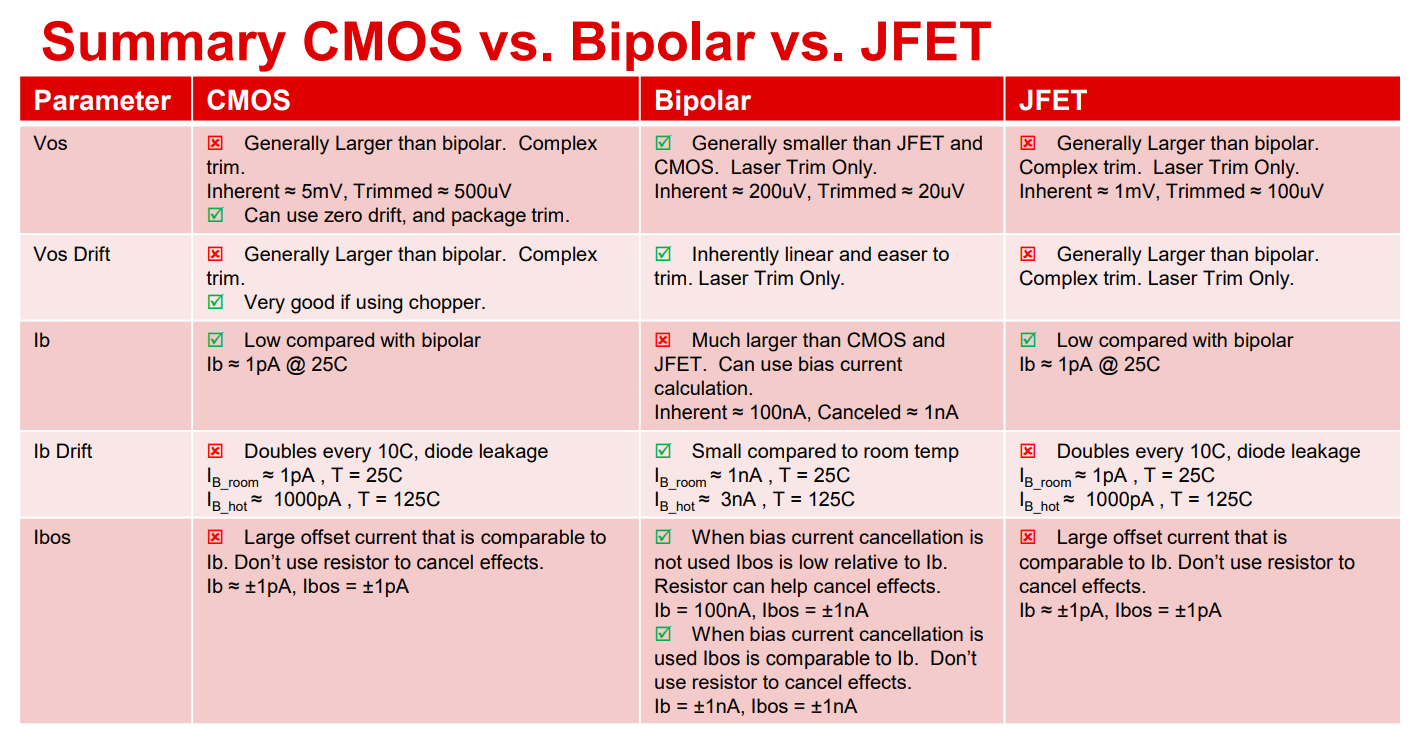
Best Regards,
Chris Featherstone
Hi Enrico,
in the following simus the input capacitance of circuit is simulated. I have done this with a 1mVpeak stimulus but different DC input voltages to show how the input capacitance is varrying with input voltage. In the first figure the DC input voltage is varried from -1V to +1V. In the second from -100mV to +100mV. On the left the circuit is shown with an ideal 2mA constant current source and on the right with the simple 8k04 resistor:
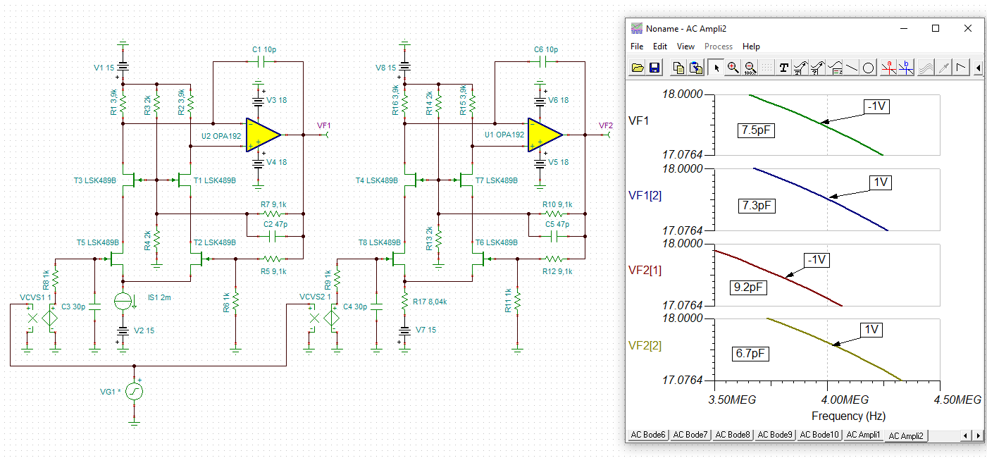
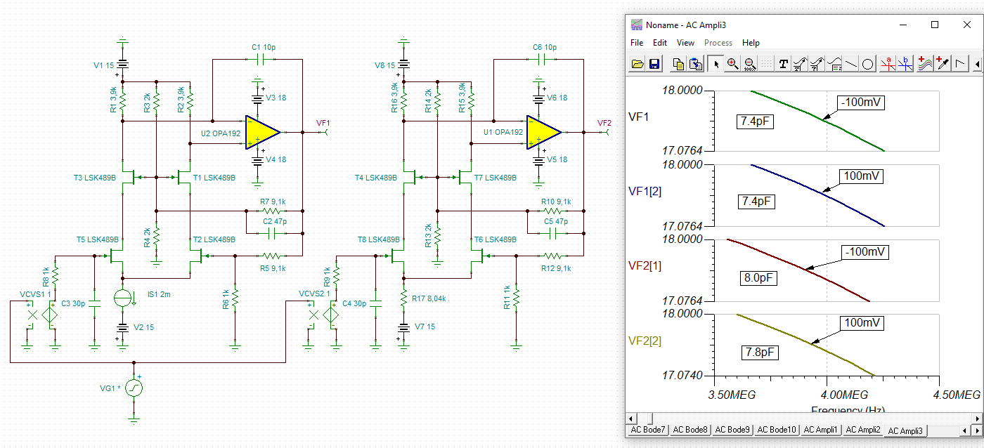
You can clearly see that the input capacitance is the more varying the more the amplitude of input signal is increasing. And you can see that the circuit with the simple resistor is showing a wider varying of input capacitance. So you can see that a simple resistor is not doing exactly the same as an ideal constant current source. But the effect is only marginal here.
This simulation demonstrates that in low input level applications a constant current source can often be replaced by a simple resistor, especially when the supply voltage is as high as in this circuit. But in high input level applications a constant current source can absolutely make sense in the first stage.
By the way, in an integrated OPAmp you will nearly always see a constant current source in the first stage, because the circuit must be able to run properly with highly different supply voltages.
Kai
Dear Chris,
how can you get the spice model of the jfe2140 to simulate in proteus?
Thanks for your reply.
Enrico,
You can download the Pspice model and I found a way online to import the model. See below. Alternatively we offer both Tina-Ti and also PSpice for Ti for free.


Best Regards,
Chris Featherstone