This thread has been locked.

If you have a related question, please click the "Ask a related question" button in the top right corner. The newly created question will be automatically linked to this question.

INA128-HT: Output Dependent with Temperature

Part Number: INA128-HT
Other Parts Discussed in Thread: INA128, INA333-HT

Hello,

I designed a Strain Gauge sensor using the INA128-HT and ADS1284-HT ADC.

The system works at room temperature with a fluctuation of +/1 bit at a 16Bit output - good for my requirements. INA128 gain is set to 100.

Touching the INA128 with my finger, makes the output to increase ~64bits. This is a problem and at 175C, the rated temperature of the system, I suppose this will be even worse.

Do you have any idea why this happens and what can I do to eliminate this problem? 


Regards,

Marius Raducanu

  • I was looking on the datasheet and the offset/temperature (3.5uV/C) x change in temperature (~10C) x Gain X 0xFFFF/5000mV is close to what I get (46ADC). I hopped that the offset doesn't change the output so much.

    Regards,

    Marius Raducanu

  • Hi Marius,

    this is absolutely normal. By touching the INA128 with your finger you will couple mains hum and EMI into the die by capacitive stray coupling. As consequence the output voltage becomes much more noisy than without doing this. Be careful, by touching the chip with your finger you will also introduce stray capacitance into the circuit which can destabilize the circuit and cause oscillation and even damage of the chip. More, you risk to destroy the chip by ESD.

    Kai

  • Hi Kai,

    Thanks for your answer.

    I suppose you are right about the capacitive noise but only increasing the temperature of the INA128 with a heater makes the output to increase with ~700ADC units - so is not only the capacitive noise, it is the offset dependent of temperature. Also, touching the INA128 doesn't create noise in output - I filter the signal before entering the ADC and the output is constant if the temperature is constant.

    Regards,

    Marius

  • Hi Marius,

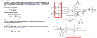
    Have you considered to place differential and common mode LPFs in front of INA128? It won't help the thermal drift, but it will filter out unwanted common mode noise. Please use NP0/G0G capacitor in C2 (differential mode capacitor) or X2Y capacitor for the filter.  

    https://www.mouser.com/ProductDetail/Johanson-Dielectrics/101X18W104MV4E?qs=sGAEpiMZZMukHu%252BjC5l7YbmdJKWhXZFo0HB0uF%252BaexM%3D

    https://www.ti.com/lit/ug/sbou115c/sbou115c.pdf?ts=1646062379734&ref_url=https%253A%252F%252Fwww.ti.com%252Ftool%252FINA826EVM

    INA333-HT  may help some with the offset drift issues, but the part's supply range is only rated up to 5.5V (INA128 is rated up to 36Vdc in a single supply rail). 

    With INA128, you may consider to autozero to remove the any offset voltage at a given temperature before measurement (or you may try it with software approach). 

    If you have other questions, please let us know. 

    Best,

    Raymond

  • Hi Raymond,

    Thanks for your response.

    The output of my INA128 + ADS1284-HT is very stable at constant temperature +/-1ADC for a 0xFFFF range. I am using filters in hardware and software (averaging 50 samples/second). My problem is strictly related with the offset changing with temperature.

    This is what I wrote in an internal company email.

    There are four ways to compensate/mitigate the output with temperature:

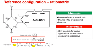
    • In Hardware: Convert the voltage reference from excitation voltage. In this way, the change in the excitation voltage will affect the voltage reference compensating with temperature. This makes the hardware less complicated but still not solve the changing offsets with the temperature. This is what we have now in the XXX design.
    • In Hardware: Keep excitation voltage, power voltage, OPAMPs (Instrumentation Amplifiers) offsets and voltage reference constant with temperature. This can be done partially with a HT voltage reference and HT OPAMPs (40mA output minimum – used as excitation). The offsets changing with temperature cannot be compensated, for instance the INA128 has an offset of  ~4uV/C. In the IRT this is ~780ADC units for 25-175C range (less than 2%range).
    • In Hardware: Use a voltage reference that compensates the change in temperature. This requires a circuit that has a gain changed by the temperature. Advantage: can provide very good analog temperature compensation; Disadvantage: needs an extra circuit and is difficult to find the exact gain to compensate the temperature (lot of testing).
    • In Software: This can be applied in parallel with the hardware compensation. The measured temperature can be applied to compensate the SG output. I tested this and works – the change in the output is proportional/linear with the temperature. The advantage of this method is that can be applied very easy, not requiring complicated hardware. The disadvantage is that XXX temperature reading is on 10 bits making the compensation to have an error of ~1C, not a big problem (less than 1% error range).

    Regards,

    Marius Raducanu

  • Hi Marius, 

    The ratiometric approach will definitely improve the design accuracy and performance. The issues are Vos is temperature drift issues in INA128 and will not be a part of the transfer function as shown in the slide below (Strain gause --> INA128 --> ADC, ratiometric configuration between Vexc and ADC). The ratiometric approach will remove the excitation voltage reference variable over temperature. 

    Below is an example of ratiometric approach in RTD temperature sensing design. Although it is used in a different application, the end of results should be similar. 

    https://static5.arrow.com/pdfs/2013/11/24/3/19/23/744/txn_/manual/slau520.pdf

    With the wide temperature operating range, you will need to remove a thermal drift offset at a given measurement temperature (just autozero or take a Vos reading without a load before the start of a measurement, and subtract the Vos from the Vout measurement). Or as you stated, the software compensation or Vos removal method should work well. If you are able to implement both hardware and software methods, then the application should be perform well within the system's required %error.  

    If you have additional questions, please let us know. 

    Best,

    Raymond

  • Hi Raymond,

    Thanks for your answer.

    What you recommended is what I have implemented in my design.

    A solution with a constant excitation (INA333-HT) and constant reference (REF5025SHKQ) maybe is a better system but requires more expensive parts.

    Thanks,

    Marius Raducanu

  • Hi Marius,

    I think that your design approach sounds good. Even with the best reference voltage IC (banggap voltage reference in REF5025SHKQ), its output will drift when operating temperature is going beyond 125C. It is a matter of %error when Tamb > 125C. With ratiometric DAQ approach, you can at least compensate for  the thermal drift. 

    As you pointed out, INA128's Vos (Vos vs. Temp) may be subtracted out at any Tamb condition, and it is predictable as temperature increases. The Vos can be removed or calibrated out at a given operating temperature and measurement.   

    • In Hardware: Convert the voltage reference from excitation voltage. In this way, the change in the excitation voltage will affect the voltage reference compensating with temperature. This makes the hardware less complicated but still not solve the changing offsets with the temperature. This is what we have now in the XXX design.
    • In Software: This can be applied in parallel with the hardware compensation. The measured temperature can be applied to compensate the SG output. I tested this and works – the change in the output is proportional/linear with the temperature. The advantage of this method is that can be applied very easy, not requiring complicated hardware. The disadvantage is that XXX temperature reading is on 10 bits making the compensation to have an error of ~1C, not a big problem (less than 1% error range).

    Your ideas to implement both hardware and software compensation methods are well thought of, and it will minimize measurement errors at higher operating temperature per the sensing application.  

    If you have additional questions, please let us know. 

    Best,

    Raymond

  • Hi Raymond,

    Thank you very much, your answer give me the confidence that my design is good.

    Regards,

    Marius Raducanu