This thread has been locked.

If you have a related question, please click the "Ask a related question" button in the top right corner. The newly created question will be automatically linked to this question.

Frequency Response of INA321

Other Parts Discussed in Thread: INA321

Hi,

I want to use INA321 as a sense amplifier to develop a current measurement tool for MSP430.

In the data sheet it is mentioned that the -3dB BW by a gain of 5 is as high as 500kHz.

I tries to amplify sense voltage having a frequency of 10kHz, with a gain of 10, 100, 50 but either one works!

The highest frequency I can get a more or less stable signal with, is 1kHz.

I attached my circuit as well as the simulation plots for your convenience.

Actually I think that the load capacitance (100uF and 10nF) which we have to connect at the input of MSP430 are the source of the trouble, but I can't find a physical explanation for that. Is this effect mentioned any where in the data sheet?


Thanks

INA321_mspbeginner.TSC
  • Hi MSP430-Beginner,

    Thank you for providing a simulation. I looked at it and saw that your graphs show the amplifier working correctly and is stable. The outputs waveforms are the amplified version of the input waveform.

    Your input square wave signal generator is going through an RC low-pass filter (LPF) that greatly slows down (skews) the input signal to the amplifier.
    To correct this you need to change the resistor and capactior values shown in the above figure so that the LPF has a cutoff frequency higher than your input signal.

    RC LPF Cutoff Frequency = 1/(2*pi*R*C).  Using R=1k and C=10.1uF your cutoff frequency is 15.76 Hz, way below your desired input signal of 10kHz.

    Can you use a smaller capacitor and resistor? Is the resistor value something you can control or is it internal to another part? 

    Regards,
    Chris


  • Hi Chris,

    thank you so much sir for your detailed reply.

    Actually the capacitors 10,1uF are the caps that have to be connected to the MSP430 at its supply line to smooth the supply voltage and remove the noise from it.So i can't take it out.

    I can't simulate MSP430 in TINA, so I used the resistor (R2 as a load) and the voltage source VG1 just so that the current at the shunt is variable with a certain frequency.

    Yes you're right, I did not pay attention that the resistor and the cap form a LPF which slows down the input signal to the amplifier.

    In TINA I found only a constant current source (To predefine how much current I want to measure), so I can not simulate the circuit with changing current with a certain frequency.

    My goal again, I want to simulate and test if the amplifier can detect every changement in the current consumed by the MSP430, especially when it switches from a power mode to another.

    Thx

  • MSP430-Beginner,

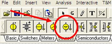
    Sorry for the delayed response. You can try using the current generator component.

    Thanks for the clarification, I understand what you're measuring now. I think you're on the right track. Just keep in mind that the whatever current or voltage glitches you apply to the power supply will be partially filtered by those capacitors (often referred to as bypass caps) which is desirable in the actual circuit.

    Best regards,
    Chris