This thread has been locked.

If you have a related question, please click the "Ask a related question" button in the top right corner. The newly created question will be automatically linked to this question.

BOOSTXL-3PHGANINV: Overcurrent protection

Part Number: BOOSTXL-3PHGANINV

Hello experts,

1. On the board you can measure the phase voltages. You can display these voltages or take them for a sensorless control. Are there any other uses for the measured phase voltage? Can it be used to monitor faults, for example?

 2. There are two methods implemented on the board for overcurrent protection

           a. hardware-method with with 3x TLV320x (see picture)


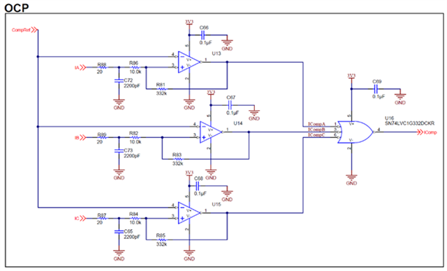
                                             (BOOSTXL-3PhGaNInv Schematic (Rev. A)

         b. software-method: phase currents -> AD converter -> CMPSS -> (trip)-EPWM

It is obvious that the first method is more expensive. But in case of overcurrent the currents can be switched off faster. The second method is cheaper and also very elegant. But is this method also fast enough to switch off the MOSFETs in case of a fault? And of course, if the second method works safely, it is the favored method for everyone. Are there perhaps situations where one should definitely use the first method?

3. In order to detect shorts of the motor windings to ground or to each other, it is necessary to measure the supply-side and/or return-side DC bus current. But on the board it is not possible to measure this currents. Is there perhaps another methods from TI to determine this currents indirectly in order  to detect the mentioned short-circuit fault?

Many thanks in advance and best regards

Bui van Linh

  • Hi,

    Please see my comments below:

    1. In the reference design, the phase voltages are used for motor control. Since these values are available, they can probably be used for other purposes including fault detection, as long as the correlation is reliable and understood.
    2. An example I can think of where the hardware implementation may be required is for very low inductance motors, where current may increase rapidly under fault conditions such as stalling. The the software method may not be quick enough.
    3. Inline current sensing should be able to detect these faults. The high side or low side total current is simply the algebraic sum of phase currents. Of course you can also measure them directly with a high side and/or a low side current sense amplifier. We offer a large portfolio for high side and low side current sensing. Here is a reference design with low side sensing.  

    Regards, Guang

  • Good Morning Guang,

    have many thanks for your feedback!

    Best Regards - Bui