Other Parts Discussed in Thread: TLV7031
Hello,
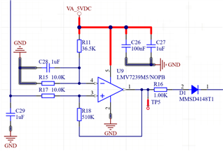
I am working on a PCB equipped with an LMV7239M5/NOPB in a non-inverting comparator with hysteresis reference design from the datasheet.
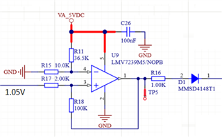
In SPICE simulation this works fine, but on the PCB the circuit oscillates when the input voltage is between 1.000 and 1.100V instead of having the hysteresis.
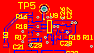
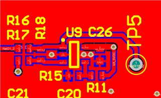
The PCB is dual layer, with GND and the 5V trace on the bottom layer and all connecting circuitry including a testpoint on the top layer.
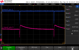
While debugging, I noticed that when the output drops from 5V to 0V, the positive input briefly rises above the externally applied input voltage. This causes the positive input to be higher then negative, and the comparator output goes high again. After an RC decay the voltage on the positive input lowers again below the negative input and the output tries to go low restarting the cycle.
I added a 10nF capacitor over R15 to make sure the reference voltage is stable, however this seems not enough. A capacitor between the input pins does have significant effect, a small one (33pF) is enough to stabilise the circuit, but the calculated hysteresis is significanlty affected. From the tests below I concluded that 1nF restores usefull operation to the circuit, altough hysteresis is still lower then it should be.
I would like to understand why this occurs and how to avoid it. What causes the positive input to rise when the output lowers?
Below some capacitor values I used between + and - inputs, together with a hystereses that is supposed to be 100mV.
C = 10pF => oscillating, no hysteresis
C = 33pF => barely stable, just 3mV hysteresis.
C = 47pF => stable, 13mV hysteresis
C = 220pF => stable, 63mV hysteresis
C = 1nF => stable, 78mV hysteresis