This thread has been locked.

If you have a related question, please click the "Ask a related question" button in the top right corner. The newly created question will be automatically linked to this question.

(Signal Conditioning Circuit) Current sensing

Other Parts Discussed in Thread: LF411, OPA348, OPA342

Hello everyone...
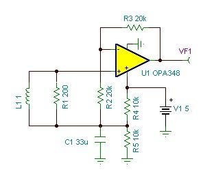
I am designing a current measurement circuit using a CT(current transformer, 5A/5mA, TA12-100).
The measured signal must be mapped into a 0-5V voltage signal for the microController's A/D to read.
However we must put a small resistance at the CT terminals, so what is the best conditioning circuit, that can translate these small voltages into amplified 0-5V.(using the LF411 or any similar device).
Can any one help me in this design.
Also any comments, advises well be highly appreciated...

  • Mohammad,

    The current transformer you cite is designed for a 200 ohm termination or load resistor. This would give a 1Vrms output for a 5Arms primary current. If one side of the CT output is biased at 2.5V, the CT might be used to drive the a/d converter directly. You would need to determine whether the 200 ohm impedance is sufficiently low to drive the a/d converter directly. The output would swing +/-1.41Vpeak around the 2.5V bias voltage, using a substantial portion of the converter's range.

    If your input currents are smaller, you may want to add gain. The circuit below provides the 200 ohm termination with R1. The amplifier provides a gain of +2 set with R2 and R3. The output is biased at 2.5V by R4/R5. C1 is an essential component used to stabilize the 2.5V bias voltage. The time-varying current through R2-R3 would otherwise cause the 2.5V bias voltage to vary.

    I recommend the OPA348 op amp.

    Regards, Bruce.

  • Mr. Bruce

    Thanks  a lot, that was so helpful.

    Best Regards,

    Mohammad

  • Hello,

    I am testing this circuit with a CT that is designed for a 1K load resistor, and it seems to work well.  However,  with R3 = 20K and R2 = 10K, the gain is measured at 5.  Can you explain the gain calculation based on R2 and R3? 

    Thanks

  • Fred,

    If the circuit is connected as shown in the figure provided a couple of posts above with R3=20k and R2=10k, the gain should be 3. G = 1 + R3/R2.

    I'd suggest that you recheck your resistor values and method of measuring gain.

    Regards, Bruce.

  • Hi Fred,

    For R3=20k and R2=10k, you will get a gain of 3, and your output will be biased by 2*2.5=5V.

    please note that these value are approximate, since the 1K resistor is loaded by R2.

    Regards,

    Mohammad

  • Thanks for the quick responses Bruce and Mohammad.  It appears that the op amp was defective. After replacing it and setting R3=R2=20K, the gain was measured at just under 2.  However, setting R3=100K did not increase the gain to 6, but only increased the output by about 10%.  The circuit is using an OPA342, but I would not expect that to be a problem unless it has a limit I am unaware of.  I am not sure the gain applies to the DC bias voltage since it is referenced to that voltage.  At least, I am have not seen that during testing.