This thread has been locked.

If you have a related question, please click the "Ask a related question" button in the top right corner. The newly created question will be automatically linked to this question.

Question on OPA361 output inductor

Anonymous
Anonymous
Guru 17045 points
Other Parts Discussed in Thread: OPA361, TINA-TI

Hi,


I would like to ask a question on OPA361 output inductor.
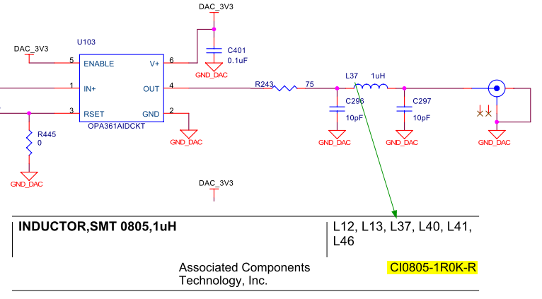


In Spectrumdigital’s EVM6437 schematics, OPA361 output connects to a 1uH inductor, which according to their BOM is CI0805-1R0K-R from Associated Components Technology, Inc. This CI0805-1R0K-R cannot be found on Digikey.com, and other Internet search result doesn’t give its datasheet.


Is there any special requirement on the inductor? If not, may I just use an ordinary 0805 1uH inductor instead?


Thanks,

Zheng

  • Zheng,

    This forum supports the OPA361 device but does not reach the C6000 group or Spectrum Digital that designed this particular EVM board. The output network C-L-C is not required in OPA361 applications. This network has a cutoff frequency around 20MHz and does not significantly affect the video output signal. A similar filter is included on virtually all the I/O connections on this EVM and may be included to prevent high frequency digital signals on the board from radiating outward.

    I don't imagine that the characteristics of the inductor are critical. You may want to contact Spectrum Digital or the C6000 forum for information on their circuit board design.

    Regards,  Bruce.

  • Zheng,

    You've asked questions that could fill a book with answers--far more than I could possibly answer in this forum. The Wikipedia links that you have shown are both applicable. The first is more general. The second is written to address the issues of filtering the output of a power supply.

    The questions you ask relate to what electrical engineers call "basic circuit theory." These filters are no more than frequency-dependent voltage dividers. They exploit the the frequency-dependent reactance of capacitors and inductors. In this case they pass low frequencies and attenuate high frequencies.

    The characteristics of a filter like this one can be approximated with a few quick calculations involving resistance and reactance of the components. Exact calculations are more tedious but can be done by hand calculations. Since I am lazy and was drinking beer at the time, I used a SPICE-based circuit simulator, Tina-TI. It can be downloaded free from TI.

    Regards, Bruce.