This thread has been locked.

If you have a related question, please click the "Ask a related question" button in the top right corner. The newly created question will be automatically linked to this question.

THS4541: 60MHz signal can be measured at the pin of FB-_1

Part Number: THS4541
Other Parts Discussed in Thread: OPA2354, THS4520

Hi, Expert

my customer use THS4541 in optical module, and have an application issue.

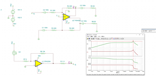
application: THS4541 convert AC single-ended signal into a differential signal. the signal is photogene rated current of pd from TIA. 
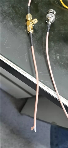
PCB:

issue:

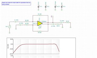
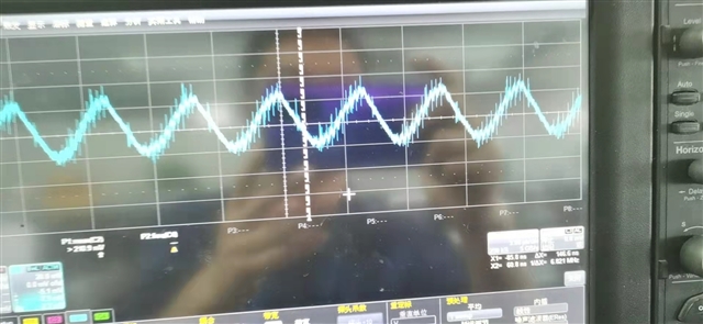
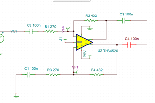
vin + ---> FB-_1 resistance is disconnected, the capacitor of output to the next stage is also disconnected, and a nearly 60MHz signal can be measured at the pin of FB-_1

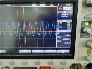
in the simulation tools, customer also could see this issue

any advice?

BR

Chi

  • Hi Chi,

    what photodetector do you use at the input of OPA2354. I ask, because you also have to take into consideration the photodetector capacitance.

    Kai

  • Your simulation shows a THS4520 FDA on +/-5V supplies, perhaps try a THS4541 on single 5V supply in simulation. 

  • Hi, Kai and Michael

    I will check with customer for photodetector, but even disconnect the input, and use signal source to provide a small signal, FB pin will oscillate.

    customer don't know how to change the model, they will have try.

    do you have any idea to prevent this issue?

    BR

    Chi

  • If you attach the TINA file, we can change it - also provide the load after the blocking caps. 

  • Hello Chi,

      Below is a simulation using the THS4541 on single 5V supply as suggested by Michael. 


      Is this the exact setup the customer is using with the TIA disconnected? Also, the customer should use a low capacitance probe, otherwise an output resistor is highly recommended to "isolate" the impedance of the probe from the output pin of the amplifier.

    0447.THS4541.tsc

    Thank you,
    Sima 

  • Hi, Sima and Michael

    Thanks a lot for your advice and test result.

    I have give the feedback to the customer, but because of COVID-19 limited, customer don't have the condition to do one more test, so I close this issue now, and will follow up when customer come back to the lab.

    Br

    Chi

  • Hi Chi,

      Thanks for the update. Once the customer can conduct further testing, feel free to reopen the thread or start a new thread.

    Thank you,
    Sima 

  • Hi, Sima and Michael

    we have test on board, also find the oscillation. here is the latest test condition, could you help to double check?

    some change: R1 and R3=7XR2, input signal is 60M sine wave, test point is left point of the C3

    test line using


    also test the point in the right of C3. input signal is 30MHz sine wave.

    Br

    Chi

  • Hello Chi,

      Are they using this circuit as an attenuator with the feedback resistor changes? With attenuators, additional compensation is needed for stability under unity. Also, it is best to probe after an isolation resistor due to the capacitance/impedance of the probe. 

      Was there oscillation with the setup including the 400Ohm feedback resistors?

    Thank you,
    Sima 

  • Hi Chi,

    hhm, why not connecting the scope this way?

    chi_ths4541.TSC

    Kai

  • Thanks for your advice. will try and feedback.

    BR

    Chi

  • Hi, Kai and Sima

    thanks for your advice, this works, didn't see any oscillation now.

    so in case there will be any more test issue, do you have any test guideline for amps

    BR

    Chi

  • Hi Chi,

    happy to hear that you were successful Relaxed

    As a guide for OPAmp measurements: Never directly touch any input or output pin of OPAmp with the scope probe or multimeter, but always insert a suited isolation resistor. The isolation resistor will isolate the OPAmp pin from any stray capacitance of measuring cable, probe capacitance or multimeter capacitance.

    For a high speed OPAmp the isolation resistor can be something between 10...220R. The higher the isolation resistance the better the isolation. But keep in mind, that the isolation resistor will also act as a low pass filter in combination with the following capacitance. Assume a 10pF probe capacitance, then a 100R isolation resistor will act as a RC low pass filter with a corner frequency of 160MHz. So, when you need to scope the output of a high speed OPAmp, it's best to connect the scope to the output of OPAmp by using the 50R technique (50R series termination resistor, 50R cable and 50R input impedance of scope.), provided the OPAmp can drive loads down to 100R.

    Medium speed OPAmps with a bandwidth of up to 5MHz will profit from an isolation resistor of about 47...470R. And low speed OPAmps like micropower OPAmps, for instance, may need an isolation resistor of even 1k...22k.

    Many users don't know that digital multimeters can have huge capacitances in the 10nF range at their input...

    To prevent scope probe ringing caused by the well known "pigtailing" effect of ground wire of scope probe, take such a ground spring:

    When using this scope probe, best solder the isolation resistors directly at the pins of OPAmp and touch with the tip of scope probe the "cold" end of the isolation resistor.

    Kai

  • Hi, Kai

    Thanks a lot. it is very helpful

    BR

    Chi