This thread has been locked.

If you have a related question, please click the "Ask a related question" button in the top right corner. The newly created question will be automatically linked to this question.

TLV8541: TINA-TI Stability Simulation

Part Number: TLV8541
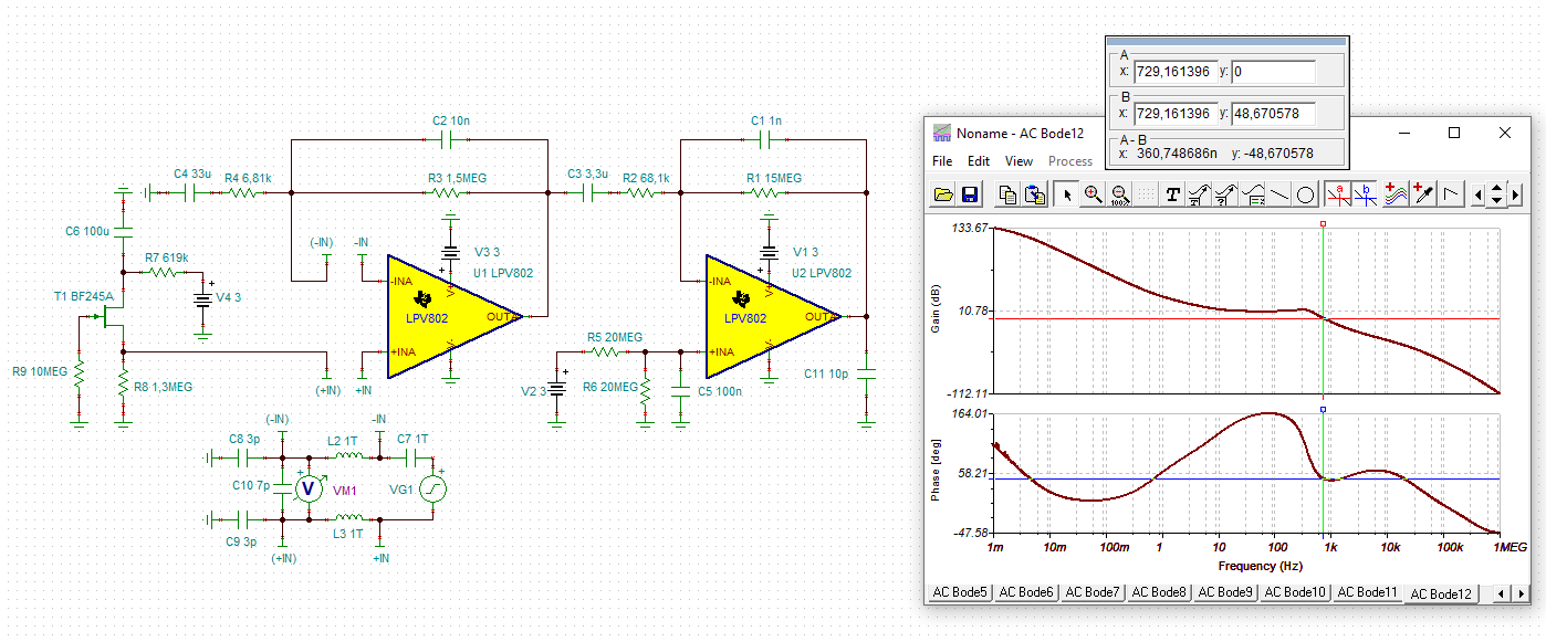
Other Parts Discussed in Thread: TIDA-00489, LPV802

Hello.

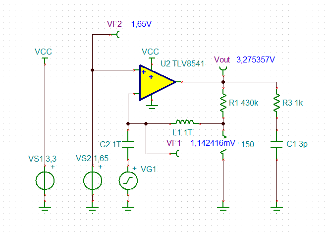
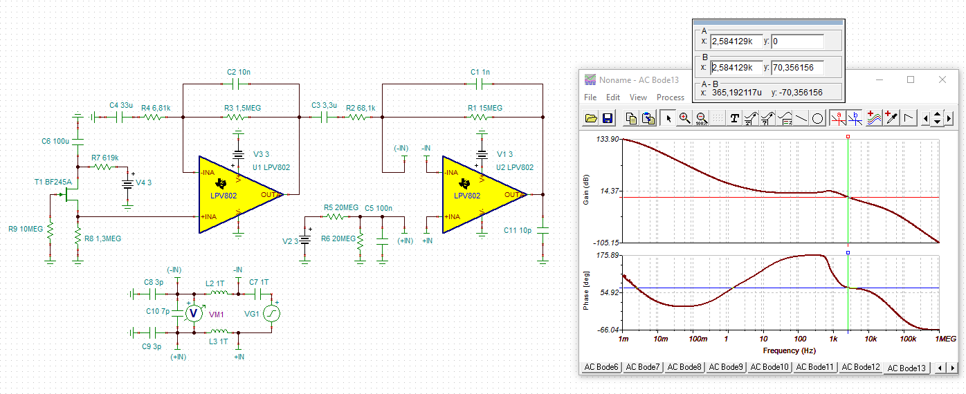
I'm attempting to prove that this noninverting amplifier circuit is stable using the method outlined in https://training.ti.com/ti-precision-labs-op-amps-stability-spice-simulation?context=1139747-1139745-14685-1138805-13850.

TLV8541_Stability_Simulation.TSC

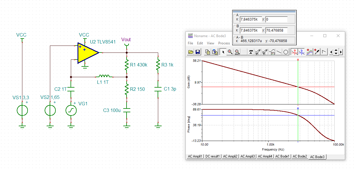
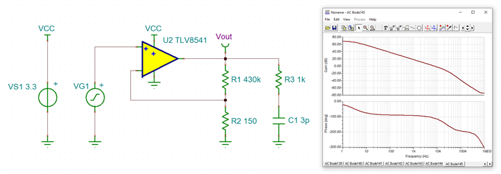
When I adjust the circuit to isolate the feedback components, the gain dives well below -280dB. This makes sense given the voltage divider, but makes it impossible to assess the phase margin at 0dB.

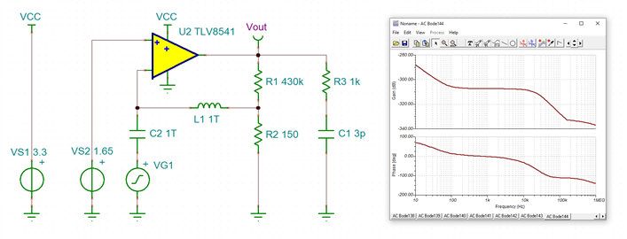
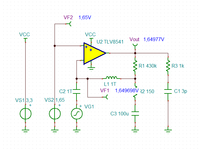
TLV8541_Stability_Simulation-modded.TSC

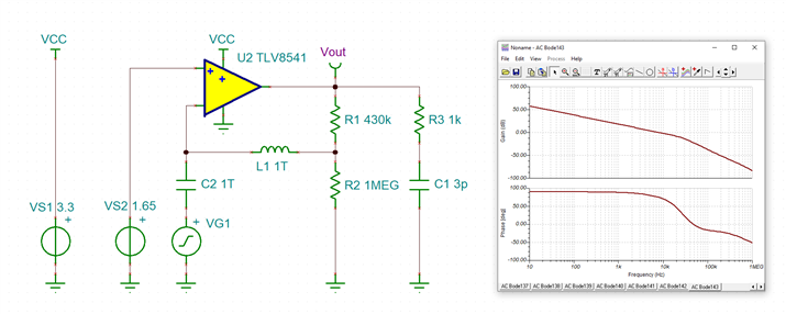
If I increase R2 to a large value, the gain information becomes useful.

1. Is this method only valid if there is no voltage divider in the feedback loop?

2. Is there are better or more accurate way to simulate stability for this circuit?

Thanks.

  • Hi Nick,

    the mistake is that you set a way too high DC gain. Even the least input offset voltage will make the output of OPAmp go into saturation then and by this leaving the range of linear operation.

    Before running a phase stability analysis you should check all DC potentials by perfoming a DC analysis first.

    Note that the OPAmp is not able to close the feedback loop in the above simu because of a too high DC gain: The both inputs of OPAmp are not sitting on the same potential.

    AC coupling in the feedback loop can do the trick:

    Kai

  • Understood, thank you, Kai!

    A couple of follow up questions -

    1. I was under the impression that phase margin was the difference between -180 degrees and the loop phase at unity gain. The analysis method above suggests that the phase margin is just the actual loop phase at unity gain. Are these the same for some reason that I'm not seeing?

    2. Does the phase margin as assessed above just need to be positive, or does it need to be greater than 45deg?

    Nick

  • Hi Nick,

    don't ovberlook the additional 180° phase shift because of connecting VG1 to the inverting input of OPAmp instead of the non-inverting input.

    Greater +45° in this plot is the aim. The more the better. In my simulation the phase margin is +70° which is very good.

    Kai

  • Kai,

    I had a seperate question, which was related to this one. The gentlemen in that post are giving me information contrary to this post. When I directed them to this, they stated that this measurement is wrong. Can you review and elaborate?

    e2e.ti.com/.../4028171

    Thanks.

  • Hi Nick,

    I only wanted to focus on that your simulation is suffering from the output of OPAmp hanging in saturation and I was relying on that you do the simulation properly after watching the training video. Sorry, my mistake Relaxed

    I will respond in your other thread.

    Kai

  • Here is what I answered in the other thread referring to the TIDA-00489:

    i Nick,

    I would do the phase stability analysis by including the JFET circuit of the PIR sensor and its output impdance and by including the input capacitances of the following comparators:

    nick_lpv802.TSC

    As you can see I get the same result as David.

    And the second LPV802 shows a phase margin of 70°:

    nick_lpv802_1.TSC

    Kai