This thread has been locked.
If you have a related question, please click the "Ask a related question" button in the top right corner. The newly created question will be automatically linked to this question.
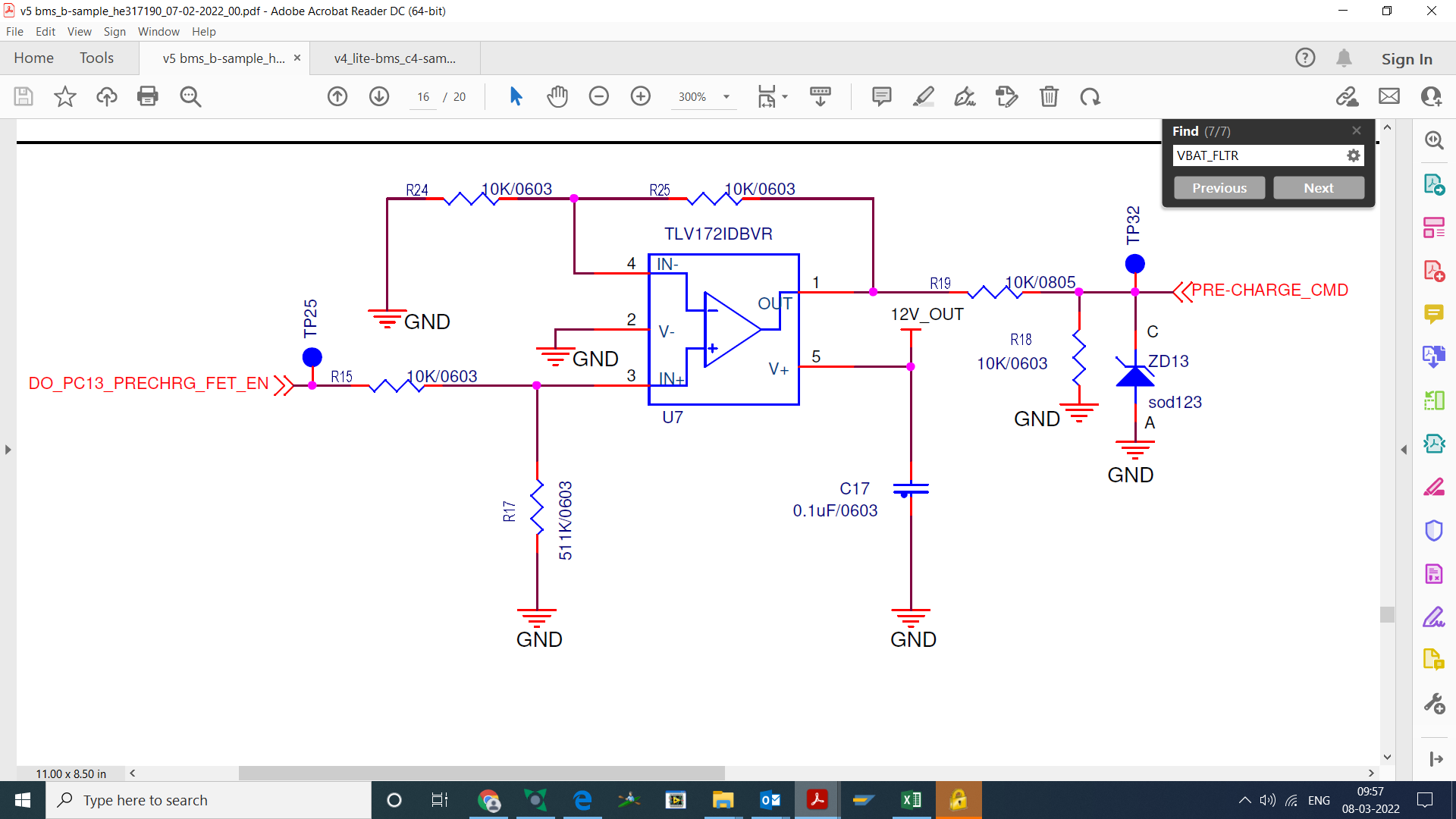
We are using TLV172 opamp as non inverting amplifier with overall gain 3.8. Even though input supply 3.3V we are getting output only 10.3-10.6V.
we are using opamp as single channel and drive with 12V supply.
But simulation results in pspice showing up-to 11.8V.
we didn't understand in practically why opamp saturated to <10.8V.
while uploading circuit in folder its not clearly visible also
Hi Santosh,
this can have many reasons. Are you using an isolation resistor at the output when connecting a voltmeter/scope? What load has the OPAmp to drive?
Please show us your schmeatic.
Kai
Hello Santosh,
My wild guess is that load is about 250 ohms to ground? (40mA output current)
Schematic please.
i sent mail though my registered ID contains data related op-amp design, simulation and also contain all parameter values in 2days before
Hey Santhosh,
I am not quite sure what your statement means. Is there a way you may upload it through here?
All the best,
Carolina
While upload the images in above box the image was not clearly visible.
Again i sent images to this mail id (noreply-e2e@mail.ti.com). just verify once.
Hi Santosh,
this will do the trick:
Or put the schematic in a pdf-file.
By the way, think about what a "noreply" email address is meaning
Kai
Hi sir, good morning
Load was 264kohm above, series resistor at op-amp output was 250ohm
R24 is 2kohm, R25 is 5.6k,
R19 is 200ohm, R18 is 263kohm.
R17 is 100K
Simulation results also attached along with circuit.
Blue colour was Vout, Red colour at R17.
Green colour at R24 with respect to ground.
Regards
Ganta santhosh
Hi Santosh,i
t's hard to help when you show two different circuits. Why is the schematic different from the given component values?
I guess the zener diode at the output of your circuit is the wrongdoer. Every zener diode lets a leakage current flow way below the threshold voltage. This leakage current causes a voltage drop across R19 and makes the output voltage decrease.
Kai
Even though zener diode zd13 removed, output voltage was shown <10.8V.
Schematic values are not updated while uploading. if you need updated schematic also will provide.
The p-spice simulation results as per schematic with updated values.
Hi Santosh,
best you take fresh resistors and a fresh TLV172 and check again. Confirm that the supply voltage is actually 12V. Confirm that the resistors have the nominal values. Keep in mind to not overload the output of OPAmp too much. What else is connected to the output? How dou you measure the output voltage? With a scope? Is the scope probe properly calibrated? What does the scope show when you probe the supply voltage? Is the 12V supply voltage stable, clean and noise-free?
Best you show scope plots from all signals. Best with a dual channel scope.
Kai
Hello Ganta,
Was the issue resolved? I will go ahead and mark Kai's response as "TI Thinks Resolved".
If the issue wasn't resolved, please let us know so we may further assist.
All the best,
Carolina