This thread has been locked.

If you have a related question, please click the "Ask a related question" button in the top right corner. The newly created question will be automatically linked to this question.

INA253: Failure modes?

Part Number: INA253

I have an issue of parts failing.

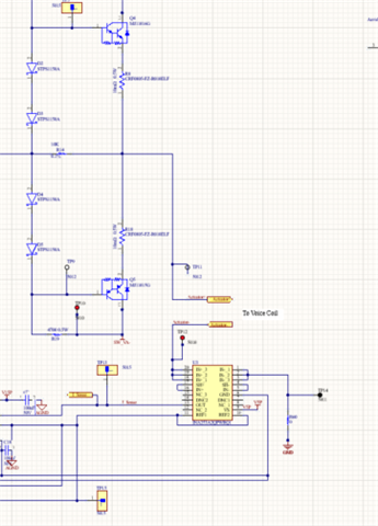
I am using the INA253A2 on the low (ground) side of a voice coil. I provides the current feedback for the Class A amplifier powering the Voice coil. The power supply for the amplifier is +/-30 volts, 3 amps max. 

The entire circuit has operated successfully for sever hours and several power cycles. It is not clear what causes the failures, but they may be associated with power on, or momentary shorts. I have been unable to trap any voltage surges at either end of the voice coil. 

After the failure the INA253 output is approximately 0 volts. The sense resistor is still functioning. when I apply a +/- 3 amp square wave to the coil I measure a 12 mv square wave at the IS+ and Vin+ pins. 

Has anyone seen this before? If I apply transient suppressing diodes to the inputs, will the performance be affected?

  • Hi,

    The common mode input voltage spec is not symmetrical WRT ground. Instead it is -6V to 90V as shown in the datasheet:

    Please double check to make sure that the input pins are not seeing the full -30V.

    Regards, Guang

  • I placed the INA253 on the ground side to make sure the common mode voltage was always low. It would take 200 amps or more through the miniscule impedance to ground to get the Common Mode voltage to -6 volts. 

  • Hi Jim,

    I see some cabling to and from the voice coil and I see a ground wire at the cold end of shunt carrying the ground return current of voice coil. These are entries for ESD and EMI. Also, inductive kickback can be generated in this cabling due to the cable inductance and the winding inductance of the voice coil itself. And there's some stray capacitance (interwinding capacitance of voice coil plus cable capacitance) where short insane voltage spikes could be injected into the INA253 circuit.

    So, I think it would be a good idea to add some protection diodes or even TVS directly at the INA253 to limit the over- and undervoltages at the INA253 to sane levels.

    As being a low side current measurement with no demand on ultra high common mode rejection, I don't think that parasitic capacitances of the protection diodes have a negative impact on the circuit. And because the measuring current is very high (3A) the leakage currents of protection diodes would have no negative effect either. But this must be confirmed by measurement, of course, eventually at elevated ambient temperatures, if ambient temperature is an issue.

    If the voice coil cable is the wrongdoer (ESD!), you could run the voice coil cable in a shielded cable and connect the shield to signal ground, best at the point where you connect the ground return current of voice coil, namley at the big fat supply voltage storage caps behind the rectifier. You could even shunt ESD running on the cable shield to the metall enclosure at the cable entry point by the help of a 10nF/1kV Y-cap.

    And you could think about moving the whole INA253 circuitry to this just discussed central ground star point. This would minimize the length and inductance of this cable running out of the shunt and to signal ground.

    Kai

  • Hi Jim,

    I see at least two grounds around INA253 – GND and AGND. Is the device ground pin referenced to GND? If not, it is not a low-side configuration.

    Also is the driver stage powered by +/-30V?

    Regards, Guang