Part Number: OPA547
Other Parts Discussed in Thread: DAC8734
Hi,
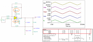
I'm using OPA547 as V to I converter with +/-15Vdc supply and a maximum current of +/- 50mA. I use 4 IC on the board in order to implement 4 V/I converter. The source is made by the 4 channel DAC8734 with the same power supply.
The output current formula is: I = -Vdac/200 and is independent form the load.
I set the current limit to approximately 55mA by adding a 390k resistor between pin 3 and 4 with a 10nF capacitor in parallel.
I tested the output current with a 100ohm load and I see on 2 of 16 boards that 1 IC limit current is below 55mA: on one board is 38mA (3,8V on the load) and on the other is 47mA (4,7V). The issue is on 2 different V/I converter
I try to solder the OPA547 but the issue remain.
The DAC output is about -10V as I expect.
In order to improve the current limit until 50mA I had to put a 120k resistor which means about 160mA current limit!
On datasheet I see a tolerance of +/- 30mA in current limit value for a load of 375mA.
Here are my questions:
1) the +/- 30mA tolerance is relative or absolute to the output current? Even if is absolute I don't understand why I need 160mA theroetical value to get 50mA output. I also try to chance the component but I have the same result (maybe also this has the problem)
2) How can I fix this problem?
Thanks