Hey TI Forums, I purchased the INA228EVM Current-Sense IC Module to use in a project of mine but I decided to test it before with a very simple resistor circuit:

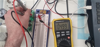
This circuit is realised in real life as shown in the image below: 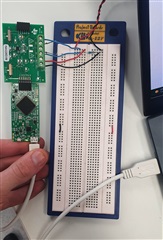
- The twisted red and black wires connect the circuit to a 5VDC Power Supply.
- The load resistor is 330Ω.
- The external shunt resistor is 80mΩ, and is connected to the EVM and the Load Current Lines as instructed by the following image from the documentation:

- VBUS is connected to the same 5VDC from the power supply, and the EVM GND is connected to the power supply GND
- As can be seen, the EVM is connected via the supplied Sensor Control Board (SCB) to my laptop (using the white USB cable) with all the appropriate drivers installed, and is successfully identified by the official GUI, as shown:

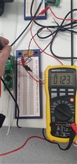
With the 5VDC provided to the circuit, a multimeter measures the expected 1.2mV across the shunt resistor (I_Load = 5V/330Ω = 15.15mA -> V_SHUNT = 80mΩ*15.15mA = 1.2mV). This measurement was made with the probes directly across the resistor and by placing the probes across the R1 solder pads to ensure the shunt voltage was being received by the PCB.
The settings for the EVM are set as shown here: 
The hardware switches on the board (SW1: SDA, SW0: SDA) match the switch settings shown in the image.
The trouble is that even though everything is receiving power (both boards LEDs are on), the EVM is successfully connected to the GUI, and the correct voltage is measured across the shunt resistor meaning that the correct current is flowing through it, the GUI still returns no reading of V_SHUNT or CURRENT, as the result page here shows:
I am left a bit confused and not sure what to do, so I'm hoping someone here might be able to offer some help and get this EVM working.
Thanks in advance,
Laurence