This thread has been locked.

If you have a related question, please click the "Ask a related question" button in the top right corner. The newly created question will be automatically linked to this question.

OPA847: opa847 oscillation for Embedded Gain Transimpedance Design

Part Number: OPA847
Other Parts Discussed in Thread: OPA855

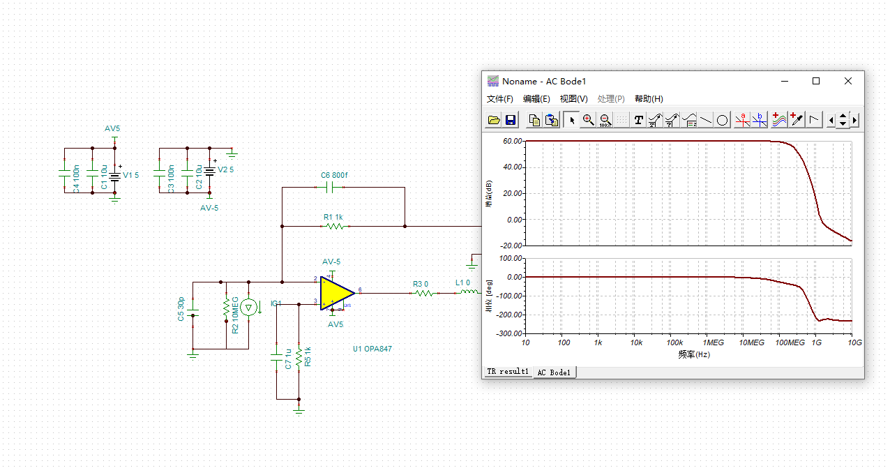
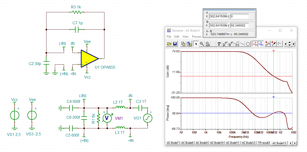
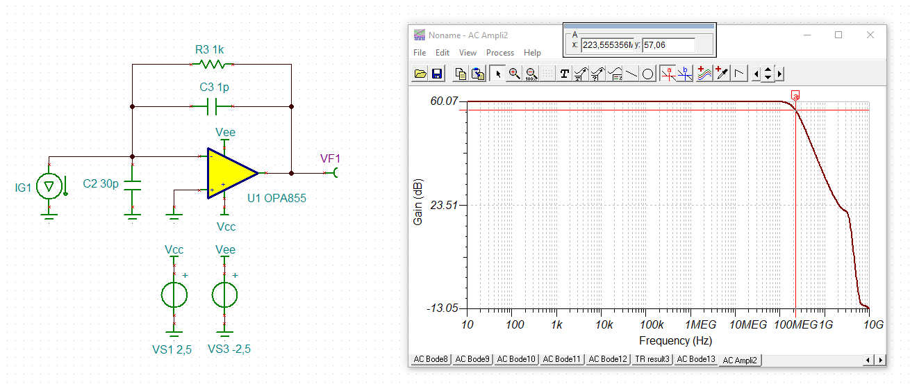
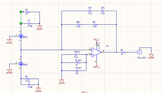
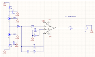
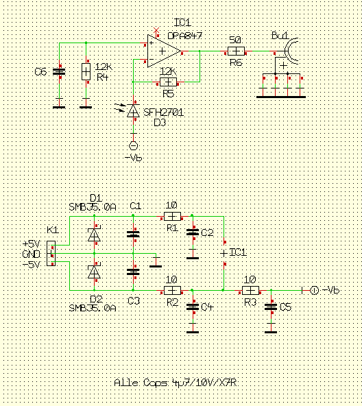
To achieve a TIA circuit with  gain of 1kV/A and 200Mhz bandwidth ,using single opa847 seems not enough, I try to use the method of  Embedded Gain Transimpedance Design which use 2 amps in its loop,such as below:

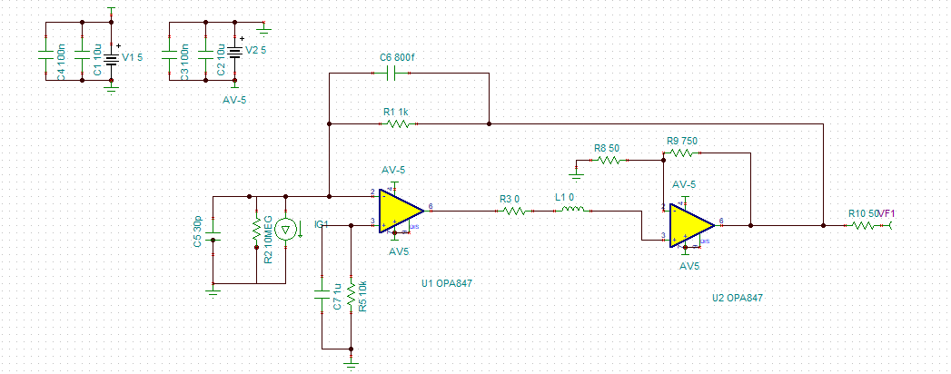
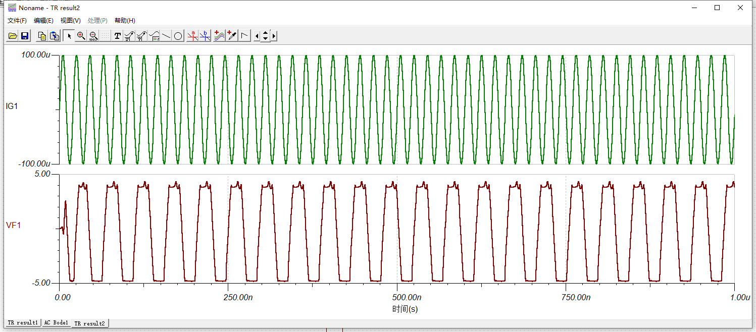
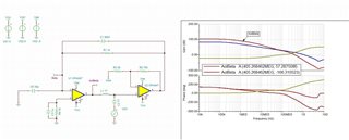
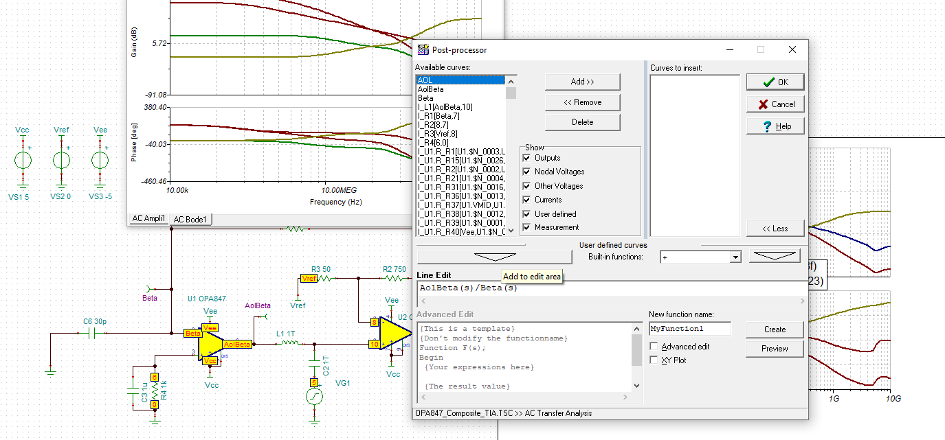
But the output is not stable in Tina simulation,as below:

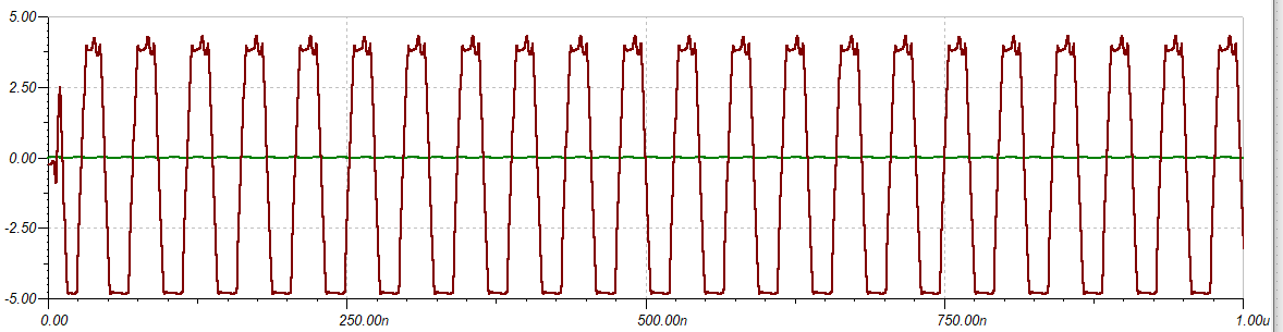
So can anybody tell me how to fix this ?And this is my .tsc file.

opa847_tia - enbeded.TSC

  • kai,

    thanks for your fast reply.

     But i wonder in the conditions of  the phase stability analysis showing sufficient phase margins,why  there still have stable issues at the output?

    opa847_tia - enbeded2.TSC

    thanks 

    bao

  • Hi Baolin,

    why not using the OPA855?

    baolin_opa855.TSC

    baolin_opa855_1.TSC

    Kai

  • kai,

    happy for your reply and your question!

    I JUST MEET this weird problem,for the same detector and the same Rf gain,but the bandwidth of the tia using opa855 is half less than opa847; i feel stranged,

    Also in practice ,the bandwidth with opa847 is less than theory 'value, it looks like the opa847 has only 2800Mhz GBP.

    this is the schs for opa847 and opa855:

    Baolin 

  • Hi Baolin,

    one cause of lowered bandwidth (and instability !) in a TIA application is the introduce of unwanted inductance between the photodetector and the TIA input. Every millimeter of copper track on the printed circuit board and every millimeter of simple wire adds 1nH of inductance. So unless the photodetector sits closest (!!!) to the TIA input you will never get the full bandwidth of TIA:

    baolin_opa855_2.TSC

    Yes, every single millimeter counts here!

    Think about using a 8MHz OPAmp. Would you think that a 1m long wiring at the -input is acceptable in a reliable and stable design? Well, I wouldn't. Now think about using a 8GHz OPAmp. An 8GHz OPAmp is thousand times faster than a 8MHz OPAmp. This means that you should shrink all the wiring by a factor of thousand. But 1m / 1000 = 1000mm / 1000 = 1mm. So what looks like a 1m wiring for a 8MHz OPAmp looks like a 1mm wiring for a 8GHz OPAmp.

    Well, I have seen many OPA855 circuits where the photodetector is 50mm or even more away from the input of TIA. Translated to a 8MHz OPAmp this would be about 50m and more. Do you think that this is acceptable? Even with a 8MHz OPAmp such a distance could cause severe issues. But with a 8GHz OPAmp it's just deadly Relaxed

    Kai 

  • Kai,

    Absolutely help!

    That theory consists with the phenominon in experiment!

    i'll redesign my circuit and test it,wish it  a good result!

    thanks a lot! 

    baolin

  • Good luck Relaxed

  • kai,
    I have redesigned my 847 and 855 circuit as below, trying my best to short the trace length where it needs,
    In test results ,i find nothing better than before ,nearly the same as before .
    IN single detector mode,the bandwidth of opa855 is 30Mhz while the opa847 is 90Mhz, the Cs is 25PF, the gain is 1kV/A,which shows OPA847 got a worse GBP of less than 2.8Ghz.
    Maybe it's the quality of res and cap or pcb that make the circuit not work well??

    this is the 3d circuit below:


    Baolin

  • Hi Baolin,

    I'm really sorry that you have trouble with the circuit.

    Ok, let's make things as simple and as conform to the datasheet recommendations as possible:

    -Keep in mind that the 50R termination resistor at the output shall not be connected to pin 1, but to pin 6.

    -Remove all the stuff at the +input of OPAmp and connect it directly to signal ground. Use three vias for the connection to signal ground.

    -Remove all the biasing stuff at the photodetectors and connect them directly to signal ground. Use three vias for the connection to signal ground.

    -Avoid using uneven decoupling caps (uneven in size and capacitance). This can cause a very heavy and undesired resonance entirely ruining the decoupling performance. Instead, take a single ceramic high cap of 2µ2 or 4µ7 in 0603 and X7R and install it directly at pin 4. Put another identical cap in parallel to this capacitor, if necessary. Make the layout of these two caps look absolutely identically. Connect the ground pin(s) of cap(s) to signal ground by using three vias to keep the parasitic inductance to the absolute minimum.

    -Do the same at pin 7.

    -Install ferrite beads and small resistances into the supply voltage lines to allow LRC low pass filter being formed. Install these ferrite beads and resistors directly in front of the decoupling caps. I prefer the FBMH1608HM601 from Taiyo Yuden. Take 2...22R resistors. Play a bit with the values.

    -Use the microstrip technique to make the copper track to the cable connector look like a 50R line. To do so, add a ground plane also on the top layer. From this additional ground plane the whole circuit and especially the decoupling measures will heavily benefit. Connect both ground planes by as many vias as possible.

    -Use a 4-layer board with additional ground planes, optionally, if you can.

    -Open all the ground planes at pin 1 and 2 as shown in figure 12-1 of datasheet.

    -Don't forget to use the thermal pad and connect it properly.

    -Don't place the circuit all too close to the edge of printed circuit board. This will degrade the performance of your solid ground plane, because signals running close to the edge do not see a true plane any more.

    To illustrate what I mean, see this example board I made a while ago for another thread:

    Kai

  • Hello Baolin,

      A very high speed amplifier in a composite loop is a challenge to stabilize even in theory. In practice, with the additional of parasitic, it is even more difficult. 

      In simulation, the composite OPA847 above does show very low phase margin:

      Would it be possible to switch designs to a cascaded TIA using the OPA855 as Kai suggested earlier if higher gain at a higher bandwidth is needed? 

    OPA847_Composite_TIA.TSC

    Thank you,

    Sima 

  • Hi Sima,

    I fully agree with you. I wasn't able to make the cascaded amplifier run stably in the simulation with a transimpedance down to 1kV/A and to achieve a bandwidth of >200MHz at the same time. With 4kV/A no problem, but with 1kV/A without any chance.

    Kai

  • hi sima,

     can you show me some reference for setting the two curves called AOL and NG in tina? I only have AOLBETA  and Beta curves.

    baolin 

  • Hi Baolin,

    you will find them by opening the post-processor:

    And watch this TI's training video to see how the post-processor is used:

    https://training.ti.com/ti-precision-labs-op-amps-stability-spice-simulation?context=1139747-1139745-14685-1138805-13850

    Kai