This thread has been locked.

If you have a related question, please click the "Ask a related question" button in the top right corner. The newly created question will be automatically linked to this question.

behavior of the INA122 in single-supply mode

Other Parts Discussed in Thread: INA122, LM27762, LM27761, LM7705, LM2776

I've been working with my TI INA122 with a couple of sources. The configuration for this issue is single supply with pin 4 grounded, pin 3 held at 3.3V, pin 5 held at 2.5V, and pin 7 at 5V. Pins 1 and 8 are unconnected so the gain is 5. Pins 3 and 4 are connected to ground through a pair of 10K resistors (though I have tried others), and of course pins 3 and 4 are connected to the source.
I have used two sources. The first is an Arduino driven 9833 board which has been set up to deliver a sinusoidal output at 10 Hz. This configuration generates a 600 mV ac signal along with a small dc signal. I have inserted a 0.1 microfarad cap on the output to get an ac only signal. The second source is a 10 Hz geophone. The 9833 source is not truly isolated since there is a ground loop, whereas the geophone source has no connection whatever to a ground.

When I run the amplifier with the geophone source, I get a signal centered on 2.5 volts which clips at the expected limits of 1 and 5 V.
When, however, I connect the sinusoidal source I get output pinned to 5V, completely driven to the 5V rail. I have also tried using the signal generator from my scope with the same result. Just on pure instinct, I pulled the 3.3V pin at pin 3 of the 122A, and I got the output sinusoidal waveform, centered on 2.5V, amplified by 5, from 1 to 4 V on the scope. From my understanding, this configuration should not work.
I then tried the 122A in dual mode (V+ 5V, V- -5V) with VCM (pin 3) = 0. Again I got the expected result, an amplified sine wave centered on 2.5 volts. I must say I'm lost for an explanation of this behavior. I get the feeling that something must be amiss with ground, somewhere. The only thing about the 9833 unit is that it has a digital and analog ground, and they're tied together.
I'm including some figures to show what I'm seeing. I'd appreciate any help you might be able to give.
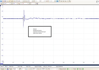
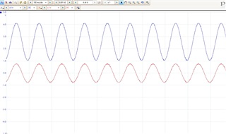
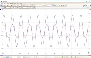
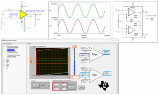
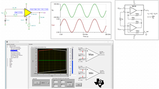
I'm including a few figures which I hope will help. Figure 1 is a trace for a geophone source with the INA122 in single supply mode. With the sinusoidal source, I haven't included a figure showing the output driven to the positive rail because it only shows 5V. However - figure 2 shows the single supply configuration with the sinusoidal source after I pulled the 3.3V Vcm off of pin 3. Finally, Figure 3 shows the output from the same configuration but with a dual +5V -5V power supply and without the 3.3V on pin 3 (obviously).
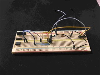
I've also included a photo of the prototype wired for single supply operation. Black is ground, yellow foreground is 3.3V to pin 3, white is 2.5V to pin 5, and in the background are the plus and minus leads for output. Input pins are at the left middle of the photo.

  • Hi Bob,

    I then tried the 122A in dual mode (V+ 5V, V- -5V) with VCM (pin 3) = 0. Again I got the expected result, an amplified sine wave centered on 2.5 volts....

    The following configuration is configured properly. With dual supply rails, your Vcm is allowed, where Vcm vs. Vout in INA122 will be operating linearly, see the transfer function in the simulation. In the marked blue rectangular box, Vin_min and Vin_max are derived for a given input setting shown in red rectangular box. On the right in turquoise color, the INA122's Vout can be driven up to ±4.9V approximately. 

    If you are interested TI's analog engineer's calculator, you may download it for free from the link below.

    https://www.ti.com/tool/ANALOG-ENGINEER-CALC

    INA122 E2E 03312022.TSC

    Regarding to a single supply rail, an input signal with proper Vcm is required as shown in the simulation below. 

    1803.INA122 E2E with single Vcc rail 03312022.TSC

    If you have additional questions, please let me know. 

    Best,

    Raymond

  • Hi Raymond,

    Many thanks,  I have both tools. I saw this example today. It looked different form what a saw a couple of days ago. I think my confusion came from the placement of bias voltages related to the non-inverting input of the 122A. Interestingly enough, a geophone source (a truly isolated ac source) can be connected directly across the inputs with the common mode bias applied to the non-inverting input and everything works as it should. The same layout with the 9833 sinusoidal source does not work at all the same way. I'm still trying to figure out why the amp clipped straight to the 5V rail. I'm going to try the circuit for the single supply I saw today from your response above.

    Best Regards

    Bob Edwards

  • Hi Bob,

    For a single supply, you need to configure the Vcm or common mode bias voltage input properly. Please use the TI Analog Engineer's Calculator to verify the input and output range of INA122. If you need additional help, please let us know. 

    If the input's Vcm is low, you may need to use dual supply voltage rail or use asymmetrical power supply rails to accommodate the input setup. 

    Best,

    Raymond

  • Thanks Raymond. I have discovered how difficult it is to find an operating range that will keep the amplifier in the linear region. As I am targeting this INA for use with a geophone source, I'll be content to apply suitable values for Vcm and Vref when the amplifier is driven by a single 5V supply, as the geophone is truly an isolated ac source. Vref = 2.5V and Vcm = 3.3V work perfectly across several gain ranges.

    I hope I didn't waste your time with my struggles with non-isloated voltage sources, but for now I'm going to stick with what works. I'm marking the issue resolved.

    Best,

    Bob Edwards

  • Hi Bob,

    You are good! We are here to support our customers. 

    The dual supply voltage rails will be the best option, if it is difficult to have a known or fixed Vcm in your input signal. If you only have single supply rail available on a PCB, you may generate the negative supply voltage from positive supply as in LM7705, LM2776, LM27761, LM27762 products, which are our charge pump LDO products. Below is an application note in LM7705. 

    https://www.ti.com/lit/an/sbaa373/sbaa373.pdf?ts=1649116674450&ref_url=https%253A%252F%252Fwww.google.com%252F

    If you have any additional questions, please let us know. 

    Best,

    Raymond

  • Hi Raymond,

    Today I found a way, just by chance to get my .6V P-P 9833 sine wave source signal through the INA 122 single supply setup. I have a dc offset of ~600 mV in the 9833 output which  accompanies the 10 Hz ac signal. With no additional DC bias from my Vcm source and no Vref, I got a sinusoidal output at a default gain of 5, within the linear range with no distortion.

    When I had earlier examined the engineers tool for the 122, I had found that the linear range was possible with a Vcm of .6 volts. It was just pure luck that the dc component in the source did the job. I can now appreciate how critical the inputs are for INA's. As I shall be using the amplifier with geophone sources, the problem of providing a suitable common mode offset is moot for single supply operation.

    Thanks for the help. I think I learned something about the subject. Consider this issue resolved.

    Best,

    Bob Edwards