This thread has been locked.

If you have a related question, please click the "Ask a related question" button in the top right corner. The newly created question will be automatically linked to this question.

INA849: output is abnormal when input higher than 5V

Part Number: INA849

Hello,

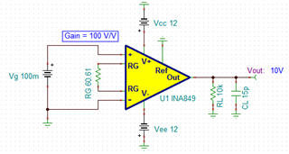
One customer used INA849 and met problem, he used +-12V  power supply, G=100, and he found that when input is higher 5V, the output is zero.  His input is DC input.

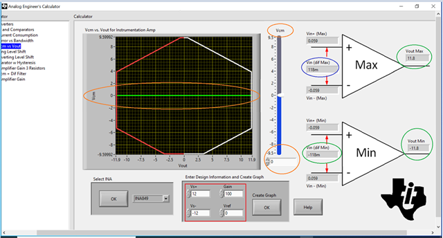
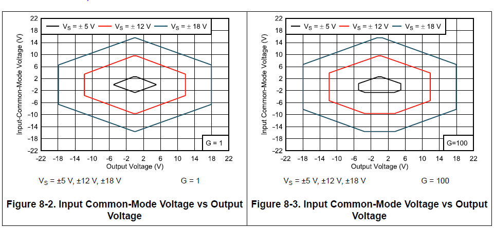
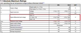
According to the Vcm  VS  Vout curve of the datasheet, the output should be about 10V.

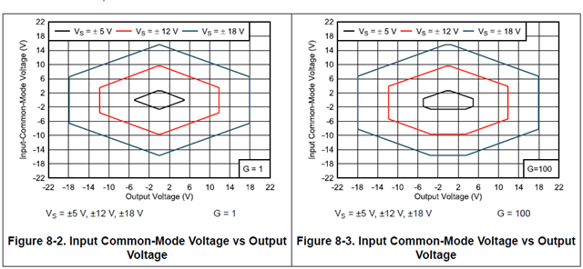
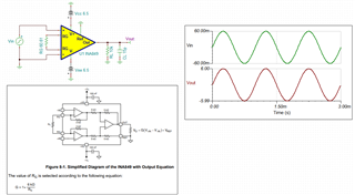
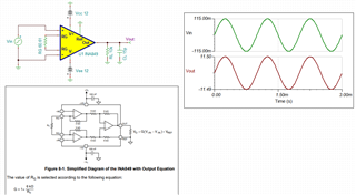
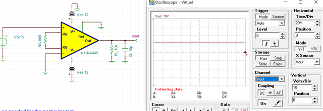
And the simulation result is the same with curve.

His schematic is as this:

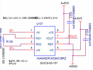
So what is the problem? Could you please help to confirm? 

Best regards

kailyn 

  • Hi Kailyn,

    So what is the problem? 

    Here are some of issues. INA849's transfer function is shown below. With Gain = 100V/V, Rg is calculated at 60.61Ω.

    2nd issue: Let us assume the schematic is using +/-12V as supply rail, with Vref = 0, the transfer function is Vout = Gain*(V+in - V-in), where (V+in - V-in) is the differential input signal. Assume that Vout can swing up to +/-12Vdc, the differential input voltage is ±12V/100V/V = ± 0.12 V or  ± 120 mV. It is not clear how you could have differential input > 5Vdc.  

    If you have a differential input voltage >5V, then Vout will be in saturation. 

    Please see the attached Tina simulation. 

    INA849 E2E 04052022.TSC

    Enclosed is the Analog Engineer's Calculator, where you are able to calculate Vin_min and Vin_max range of the differential input voltage. 

    https://www.ti.com/tool/ANALOG-ENGINEER-CALC

    If you have additional questions, please let me know. 

    Best,

    Raymond

  • Hi Raymond,

    I understand your meaning, and the customer thinks it would be output  in saturation instead of 0V when 5V input and G=100. 

    What he referred is Figure 8-3. Even though it is saturation, it should be output clipped wave. 

    In addition, I have installed the Analog Engineer's Calculator downloaded on website,  but there is no INA849. Is it the newest version? 

  • Hi Kailyn,

    Please provide us the complete schematic. 

    In the simulation you posted with Rg = 665Ω, Gain = 10.02 V/V and output is railed to 12Vdc, which is correct. 

    In the next attached schematic, Rg= R136 is calculated to be 100Ω or gain = 61 V/V, dual supply rails at ±6.5Vdc. 

    Per your circuit description, the input violates the Vcm requirements. 

    If you have additional questions, please let us know. 

    Best,

    Raymond

  • Hi Raymond,

    Thankyou for your reply, and I am sorry to make you confused. The customer has replied me that in actual circuit, 6V5 connected 12V, he used +-12V  supply, and the gain resistor Rg changed 61ohm or 62ohm, but the output is always zero, he tried several INA849 and has the same results.

    So he'd like to confirm with this question.

    Best regards

    Kailyn 

  • Hi Kailyn,

    Can you ask the engineer to configure INA849 circuit as shown below? I want to know what is the output of INA849. The following circuit is operating at linear region. I was wondering if the INA849 is damaged, and is able to operate linearly. Please see the absolute max. ratings in INA849. 

    If INA849 is still able to operate linearly, please send me the actual lab configuration of the circuit, including the input and output of the setup.   

    Best,

    Raymond