This thread has been locked.

If you have a related question, please click the "Ask a related question" button in the top right corner. The newly created question will be automatically linked to this question.

ESD and Short to battery/ground protected opamp buffer selection

Other Parts Discussed in Thread: TLE2141-Q1, LM7705, TMUX7462F

Hi,


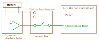
I need to protect multiple (40pcs) 5V level analog outputs against to ESD and Short to Battery/Ground failures.
This is an automotive system (ECU test device) and the battery is 12V or 24V level. It will be good to protect up to 36V shorts.

I think the best way to do this using voltage follower configured opamps that supplied by battery voltage.
Some opamp datasheets states that capable of continuously shorted to either supply in the dissipation ratings.
I'm not prefer to use heatsink but possible.

In short my requirements;
- 36V or more single supply,
- Opamp output max current rating may be 25mA or more,
- Input common mode range must include 0V-5V range,
- Outputs must be shortable (continuously preferred) to either supply,
- Outputs should be protected to ESD (no need to comply with any standard but should be durable)
  Additional ESD protection devices not preferred but possible.
- Multiple packaged versions are better, I prefer quad versions.

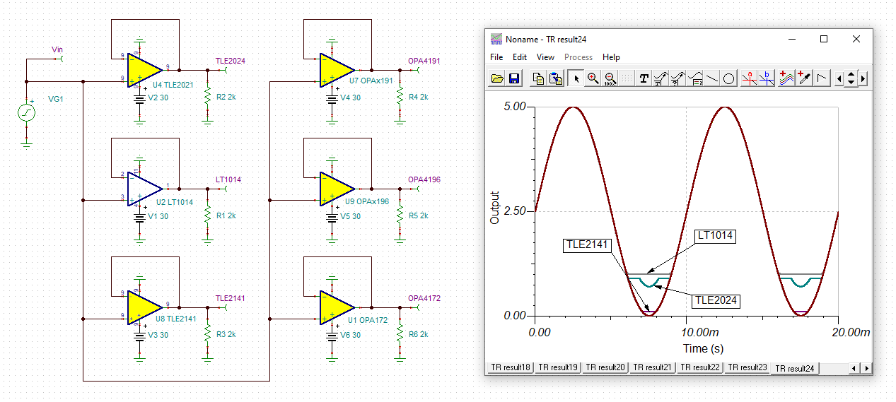
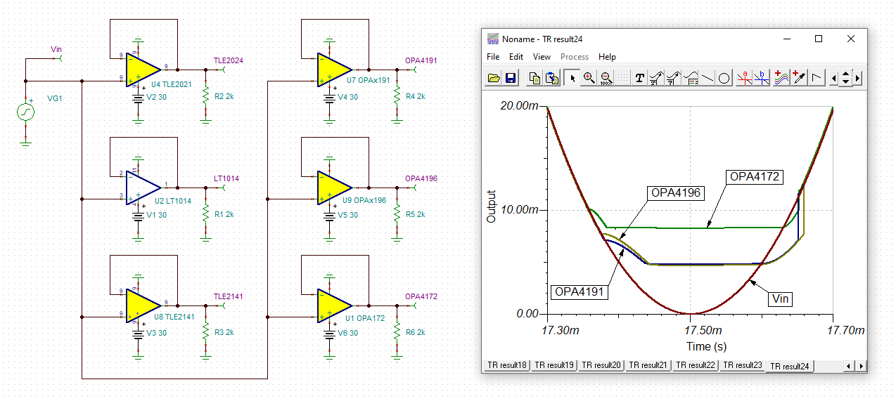
I have checked following devices;
TLE2024AMDW : ESD ratings are not specified in the datasheet
OPA4191IDR : Only short to ground specified, Short to V+ is not
OPA4172IPW : Only short to ground specified, Short to V+ is not
LT1014DMDWREP : ESD ratings are not specified in the datasheet
OPA4196ID : Only short to ground specified, Short to V+ is not

Do you have better alternatives for this requirements?

Regards

  • Hi Ibrahim,

    you should read the ISO 16750-2.

    Kai

  • Hi,

    Thanks for the document proposal.
    I don't think I need to follow that requirements, they are too much.
    My test device will neither be used in the vehicle nor test the ECU hardware.
    Main purpose of it simulating the ECU inputs for the ECU application software tests.
    ESD protection and Short to Batt/GND protection are enough for me I think.

    Regards

  • Hello Ibrahim,

    It looks like you have narrowed the op amp selection for your application well. Based on your stated requirements the TLE2024AMDW comes closest to meeting all of them. It looks to be the most suitable op amp within our product line that meets all the requirements.

    The LT1014DMDWREP may work, but the 25 mA output current requirement may become a limiting factor. The OPA4191IDR and OPA4196ID only specifies output shorts to ground, and shorts to the supplies are not assured so no assurances about that condition can be made. The OPA4172IPW is a General Purpose op amp and outside of our product responsibility. Please contact the General Purpose op amps e2e for information about that product.

    Another to consider is the TLE2141-Q1,an automotive rated op amp. However, the minimum short-circuit output current is specified as 20 mA in the product bullets so it could fall a bit short on the 25 mA output current. Keep in mind that most precision op amps aren't usually required to drive high output current loads (<~.10 mA). Op amps that require high output current output are usually specified as such.

    https://www.ti.com/lit/ds/symlink/tle2141-q1.pdf

    If you would like to pursue using the TLE2024AMDW, TLE2141-Q1 or the LT1014DMDWREP, I can contact our Quality department and see if they can provide their ESD information. They are older products so if they do have ESD information on file it will likely be limited to the HBM and MM tests.

    Regards, Thomas

    Precision Amplifiers Applications Engineering

  • Hi Ibrahim,

    keep in mind that a usual single supplied OPAmp with the negative supply voltage pin being connected to 0V cannot fully go down to 0V at its output. And even if the saturation output voltage is very close to 0V, the OPAmp performance like the linearizing open loop gain or the speed begins to degrade at some higher output voltages. In the following simulation a 100Hz sine wave input signal swinging from 0V to 5V can be seen:

    And with zoom:

    ibrahim_tle2024.TSC

    If the output voltage really must go all the way down to 0V, one remedy is to use a small negative supply voltage at the negative supply voltage pin, for instance provided by the help of LM7705.

    - Opamp output max current rating may be 25mA or more,

    What do you exactly mean? That the OPAmp shall be able to source and sink an output current of at least 25mA? Or shall it provide an output short current protection limiting the output current below 25mA?

    - 36V or more single supply,

    36V times 25mA short circuit current gives a heat dissipation of 0.9W. This will dramatically heat up the OPAmp and can be deadly for a quad OPAmp, if more than one output is short circuited at a time.

    What is the exact load such an OPAmp has to drive? What is the load resistance and what is the load capacitance? Has a cable to be connected to the output?

    Also, what is connected to the inputs of these OPAmps? Can input voltages outside the 0...5V range arrive? What about ESD? Again, are cables connected to the inputs?

    Kai

  • Hi Kai,

    Sorry for the late response, I'm very busy these days and still searching the best option for this issue.

    You have pointed out an important issue that I forgotten to check. Thank you.
    Minimum output voltages beyond 0.5V is completely useless for my application and min 10mV is very fine.
    Zero to 0.5V range is "out of range" region for most of the 5V analog sensors.
    I'm not prefer to use negative supply.

    I'm driving the ECU analog sensor inputs. They have 1k to 100k pull up or down to GND/12V/24V/5V.
    In this case the worst scenario is 1k pull-up to 24V when the opamp output driving to zero volt requires 24mA.
    Only a few pins requires this much current, most of them requires only a few mA current.
    And these pins are exposed on the breakout box, so the user may short that pins to the either rail mistakenly.
    Most likely the short duration will be a short time, but if the user don't notice the short due to the misconnection, longer short durations possible.
    One short in a multi channel device is OK.

    36V is the overvoltage condition for short periods. Normally battery boltage 24V or 12V.
    In 24V versions 25mA is corresponding to 0.6W, but if the opamp output more current capable, then more power will be dissipated.

    Opamp inputs are safe, will be connected to the 5V DAC outputs on the PCB.

    The ideal device for my situation is a overvoltage protected analog switch,
    that is no need to current consumption if the output shorted to beyond 5V, disconnection is the best method.
    But I couldn't found a device like that feature in my voltage levels,
    So I'm investigating the opamps if any device available to meet this requirements.

    Thanks, Regards,
    Mete

  • Hi Mete,

    even if an OPAmp is used which provides a short circuit protection, I would make it impossible to directly touch +24V or 0V in the switch box anyway, as shown below:

    With this scheme when installing the desired pull-up or pull-down you can never directly touch +24V or 0V and the current is always limited by the permanently installed 1k resistors.

    Kai

  • Hi Mete,

    Adding to Kai's comments; most IC's are internally protected only against output shorts to voltages within the power supply (positive and negative) used to power IC, which results in the output sinking/sourcing a short-circuit current, Isc.  However, any shorts to voltages beyond IC supply voltages will most likely result in the forward-biasing of one of the ESD protection diodes located between the output and one of its rail, and thus it will NOT be protected by internal Isc circuitry and may result in damage to ESD structure unless current is limited by external means - please read the application note under link below. Even though this application note addresses a single supply conditions found in most automotive resolver circuits, a similar protection schemes may be implemented in a dual supply applications. Likewise, similar schemes may be used more broadly to protect any analog IC from various fault conditions caused by accidental shorting of its output to voltages beyond supplies used to power it.

    https://www.ti.com/lit/an/sboa447/sboa447.pdf?ts=1616630049631&ref_url=https%253A%252F%252Fwww.google.com%252F

  • Hi Kai,

    Thanks for your proposal. My situation is not same.
    BreakoutBox and the ECU are not touchable, I'm only designing the simulator device.
    Users will need to test Short faults on the sensor pin at ECU side by the BreakOutBox.
    Inserting these S2GND/S2Batt faults is frequently needed in ECU application software development.
    And a flying wire will be used by user to short and doing wrong side short possibility is high during the tests.
    So protection for direct touch between the battery and the opamp output needed.

    Thanks, Regards,

    Mete

  • Hi Marek,

    Thanks for the explanation.
    In my condition the opamp supply voltage is same voltage with the output short voltage.
    So additional diodes like in the document are not needed I think.

    Regards,
    Mete

  • That is correct.  If the IC supply voltage and output short voltage are the same, the internal short-circuit protection should work properly and thus you do not need to implement any external protection schemes discussed in the application note.  That is UNLESS the IC has no internal thermal protection and the power dissipation inside the package (under short-circuit conditions) may cause junction temperature to exceed the absolute maximum value specified for the IC (typically 150 deg C).

  • Hi,

    I have found a perfect fit protection device for this issue, TMUX7462F.
    There is also an alternative part exist, ADG5462F, but the ti's device has better specs.

    Thanks for your proposals. Thomas's answer is the most appropriate answer to this thread.

    Best Regards,
    Mete