This thread has been locked.

If you have a related question, please click the "Ask a related question" button in the top right corner. The newly created question will be automatically linked to this question.

INA827: outputs not one-to-one with input

Part Number: INA827
Other Parts Discussed in Thread: ADS8684, LM2904

Hi TI,

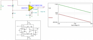
We're seeing some odd behavior while connecting an INA827 to an ADS8684.  The attached, simplified schematic shows how we 1) take measurements from photodiodes 2) connect the photodiodes to transimpedance amplifiers, 3) MUX the multiple amplifier outputs into a single INA827, and 4) connect the output of the INA827 to an input on an ADS8684.  This allows us to multiplex many, many photodiodes to a single INA/ADS measurement system.  However, we are finding some odd behavior.  Specifically, the output of the INA827 (and input to the ADS8684) gives different output values for the same input (on its inverting input).  To put numbers to it: with the photodiode in the dark, we always get 5V on the inverting input (measured with a multimeter).  The output when this is the case is either 4.01V (as expected; the ADS reference voltage is 4.096V) or, sometimes, ~4.3-4.4V.  We only see errant values after switching through many MUX channels, and we are only performing multimeter measurements with the MUX held on a static channel.  We're wondering: is there any way we may have damaged or misconnected the INA such that we could see different outputs for the same input?  We have confirmed the value reported by the ADS with a multimeter in both cases.  We have also confirmed a stable 5V power supply via oscilloscope measurements.  In terms of diagnosis, we think that our next steps will be to 1) measure the inverting input of the INA with an oscilloscope to confirm its stability and 2) sever the connection between the INA and the ADS and see if we can reproduce the problem.  Do you have any other suggestions?

Thank you in advance for your time!

Dan

INA_mini-schematic.pdf

  • Hi Dan,

    what do you see when you disconnect the outputs of LM2904 from the X0 and X1 pins and instead connect +5V to the X0 and X1 pins?

    Have you considered that the LM2904 show an input bias current of up to 250nA? This current will flow across R1 and R2 and cause voltage drops. And not to forget the input offset voltages of LM2904. So, even in full darkness the output voltages of LM2904 wouldn't be exactly +5V.

    Kai

  • Hi Dan,

    I would check with the TIA (I-to-V) individually with INA827 as Kai suggested. 

    My guess is that the input is not meeting INA827's common mode's requirements. Per your schematic, assume Vcm = 5Vdc, INA827's differential input voltage range is approx from -0.7992Vdc to 1.551Vdc, see the TI Analog Engineer's Calculator's result. You may download the tool in the link below. 

    https://www.ti.com/tool/ANALOG-ENGINEER-CALC

    If I simulated INA827's input condition presented from the input range above, the following differential input (Vsensor) vs. Vout in linear relationship is obtained. Outside of the differential input Vsensor range, Vout relationship will not be linear and you may see strange behavior from INA827. 

    In addition, ADS7684 is only ranged up to 5Vdc, so the actual INA827's output range reported by the ADC will be even smaller, see the Tina simulation. 

    INA827 I-to-V 04112022.TSC

    If you have additional questions, please let me know. 

    Best,

    Raymond

  • Hi Kai and Raymond,

    Thank you both for your thoughtful responses.  It turns out that 1) the INA is working perfectly and 2) measuring its inputs/outputs with a scope was what we needed to do all along.  We had some ringing that developed from our power supply that increased with the size of the system load.  That propagated to the LEDs that we're measuring with the photodiodes/transimpedance amplifiers, giving a huge oscillation in the INA's input.  Adding more capacitance to the power supply output fixed the problem, and we're all good now.  I'm sorry for taking up your time, but I very much appreciate your guidance!

    Thanks,

    Dan

  • Hi Daniel,

    thanks for the feedback!

    And good luck Relaxed

    Kai