Other Parts Discussed in Thread: ADS8684, TIDA-00753, , INA214
Hello,
I am designing a new current measurement device. But I am measuring 1.251V on ADS8684's both AIN_N and AIN_P pins.
Here are my design notes:
- I am using a current transformer. Here is the datasheet: https://cdn.ozdisan.com/ETicaret_Dosya/480697_631942.pdf
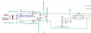
- My current measurement analog circuit is based on TIDA-00753. Here is the schematic:
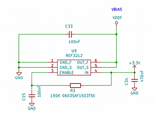
- This is my reference voltage circuit:
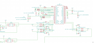
- INA199's output and reference voltage is tied to ADS8684 pins:
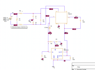
- Before designing, I made some simulations using PSpice for TI. I don't have INA199 in my PSpice library, so, I used INA214 in my simulations. The current transformer range is 0-10A and it has 1:1500 ratio. At 10A, I will get 0.0066V. I used 0.0066V sinusoidal signal to my simulations.
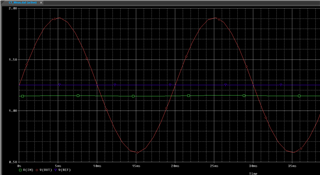
- My design measures 3-phase currents. The microcontroller's console output prints ai1, ai2 and ai3 values for first, second and third phase analog values.
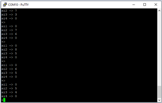
As you see the console output above, there is no value while 0.7A current flows inside the current transformer. I am measuring 1.251V both on R4 and R5.
Could you please make comment why I am not getting as my simulations?
Best regards,
Onur


