This thread has been locked.

If you have a related question, please click the "Ask a related question" button in the top right corner. The newly created question will be automatically linked to this question.

OPA191: OPA191IDBVR OPA187IDBVR

Part Number: OPA191
Other Parts Discussed in Thread: OPA187, OPA192, OPA196, OPA197

I have used the OPA191 in our designs with very good results. Due to world wide shortages, I am looking at using the OPA187 as a replacement. Other than the slew rate, what are the major differences between these two precision op amp? The application is a unity gain buffer (OPA191) of a slow moving signal that feeds an isolation amplifier with differential output that feeds a differential to single ended conversion circuit (OPA191). Sorry for the bad image. The front end has a 60-75KHz low pass filter and an 80Hz low pass filter on the diff to single ended converter on last stage, right side of circuit. Your feedback is greatly appreciated.

  • Hi David,

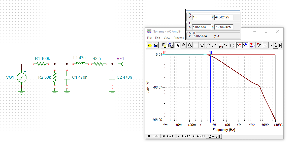
    the input low pass filter seems to have a corner frequency of 5Hz?

    david_opa191.TSC

    The OPA187 is way slower than the OPA191. This can be a problem, if you drive an ADC with U606. Depends a bit on the sampling fequency. (By the way, R606 should not be zero. A big capacitive load at the output of an OPAmp can cause stability issues and an isolation resistor would be needed.)

    Another restriction is that the OPA187 is no input rail to rail OPAmp. According to the datasheet, the input voltage should stay 2V away from the positive supply rail. If this is a problem depends on the output voltage of U605 and on the input voltage of U604. (By the way, the 0-100V input voltage range seems way too high for the scaled 0-2V input voltage range of U605.)

    Kai

  • Thank you Kai for the prompt response. The original circuit did not have the high resistor values reducing the input voltages. This circuit is crude but effective. I did simulations and changed the LRC values  and raised the cut-off frequency to appropriately 3-5KHz. I also changed the OP amp to OPA192 very similar to OPA191. The input voltage is clipped (20V)  by the diode to the power rail, and the output is scaled down. Thank you for all your support. David

  • The input clipping at 20V means that your measurement is only good up 20V - perhaps you should use R608/R614 of 100k/25k to scale it down to the op amp's input voltage linear range and prevent turning on of the Zener diode, D603. This would allow you to properly measure the input voltage up to 100V.

    As Kai mentioned, OPA187 is a vastly different op amp - in addition to much lower GBW and non-rail-to-rail input voltage range, it is a chopper amplifier, which typically should not be used with high input impedances.  Having said that, OPA192, OPA196 and OPA197 are very good alternatives to OPA191.

  • Thank you Marek for the feedback. The circuit clips at 20V as it is necessary to do so due to the IC ~max VCC. We want as much of the full scale input voltage available for our feedback circuits. We do not need to measure above 20V and hence the signal is clipped. Generally the circuit has an open circuit voltage of 80-100V but in operation the input range is either 2-18V, where the diode does not conduct, or 5-60V range where the diode still will not conduct due to the 1/3 input scale. There are two very similar circuits and the diode is there just for over voltage protection.