This thread has been locked.
If you have a related question, please click the "Ask a related question" button in the top right corner. The newly created question will be automatically linked to this question.
Hi,
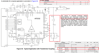
we're currently struggling some issue with AFE032. On some of our boards we have problem that after receiving first few packets our PA Output going down, we see short circuit to GND on PA Output and AFE032 internal temperature reaches about 100 Celsius without sending any data. Receiver works still fine but we cannot send any data because PA Output didn't send anything. What may cause such problem?
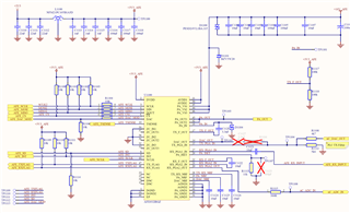
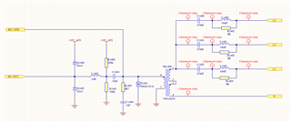
We're supplying AFE032 with 18V DC and our coupling circuit looks like this:
We're using external DAC from MCU.
Hi Kacper,
maybe your AFE032 is damaged? Have you cheked with a fresh AFE032?
Table 79 of datasheet of AFE032 recommends 3A Schottky diodes at the output of PA while you took 1A Schottkys. Datasheet also recommends a TVS with lower threshold voltage as you picked. And the break down voltage of your D1100 is also way too high, compared to the datasheet recommendation.
By the way, have you scoped the output of PA? Is the transformer properly chosen? Can you measure the output current of PA? Can you measure the current consumption of AFE032?
Kai
Hi,
AFE032 is damaged, that's true, replacing with new one helps and definitely it's AFE032 power amplifier which fails. But why is he breaking when receiving packets, so when PA is turn off?
You're right that we use schottky with lower current, we'll change it in next revision. About TVS voltage I choose it suggested by your reference design where you use 15V PA_VS and 10V TVS diode on PA output. But we can change it if that may cause the problem. D1100 shouldn't be a problem, it's a diode for PA_VS protection but it's parallel with Zener diode with 20V voltage.
I can try to measure output current of PA, I'll let you know.
But as I mention before, strage is that PA is breaking when AFE032 is in RX mode. We had that situation on 5 different boards till now and we're 90% sure that it happens when we're receiving packets.
Hi Kacper,
Thanks Kai for the reply.
AFE032 is damaged, that's true, replacing with new one helps and definitely it's AFE032 power amplifier which fails. But why is he breaking when receiving packets, so when PA is turn off?
When AFE032's die's junction temperature exceed 165C range, it will perform an automatic thermal shutdown. It looks that AFE032 is shorted at its output when Rx is activated.
it is not clear how AFE_RX_INPUT is connected at pin27 or RX_PGA1_IN node. Yes, it is capacitive coupled with C1121 or 10nF, which is only blocking DC voltage or DC short. What happen about AC short at output of PA or pin41&42 (PA_OUT1 & PA_OUT2). There are supposed to be bandpass filters at the input of AFE_RX_INPUT, see Figure 17 of the AFE032's datasheet.
Although it is stated as optional BP filter, the input impedance has to be high at high frequency. Assumed that the Rx frequency is operated near 350kHz range, its impedance has to high enough so that PA_OUT will not be shorted at higher Rx frequency.
There are other things that I do not understand. Yes, PA_OUT is shared a path between Tx and Rx nodes at the transformer. PA_OUT and RX_PGA1_IN nodes are capacitive coupled. If PA_OUT node has a short, it won't be DC voltage. It is likely shorted in AC voltage (speculation).
The RX signals sent by another transmitted PLC module after reaching the transformer has very weak AC signals (say @350kHz) in low voltage amplitude and low current on the primary of the transformer.
Could you describe what voltage and current are seen at PLC transformer's primary and secondary windings? The schematic is shown in N, L1, L2 and L3 and it must be 3-phase AC source of some kind. Secondary winding's inductance in 750510476 PLC transformer is approx. 800nH (primary is approx. 400nH @100kHz) based on its datasheet.
Let us assume that 3-phase frequency is running at 60Hz, the 2nd winding's impedance is approx. sL = 2*pi*f*800nH = 0.3 mΩ at 60Hz. 470nF @60Hz is approx 1/sC = 1/(2*pi*60*470nF) = 5.6kΩ. 10uH @60Hz will have impedance at approx. 4mΩ. Sorry, I am unable to estimate this way, since the inductance values are specified at 100kHz, and inductance figures at 60Hz are not specified.
I noticed that your transformer is swapped from the primary and secondary windings in the schematic. BTW, I do not recommend to interchange secondary as primary and vice versa in the transformer. I do not have complete transformer design parameters, but I know that pins 1-3, 2-4 are defined as primary windings and pins 7-8 are designed as secondary (by design). The leakage inductances in the transformer are optimized when it is designed as such. It may be ok to reverse the pinouts for the PLC application, but it will be better to ask the manufacture for advise or characterize the transformer on a bench to see possible deficiency. All the customers are using the intended primary and secondary sides per manufacture's recommendation. I do not have any data to support your transformer configuration.
Please provide me with additional setup information, and we will help you to figure it out what is actually going on in your setup
Best,
Raymond
Hi Kacper,
Please measure the current go through 2nd windings of transformer. You may try to decrease 470nF capacitors to 4.7nF - 10nF, if 60Hz AC current is high. What is the Rx communication frequency?
Based on the schematic, the I_lim of the schematic is configured for 0.9A, see the captured image above, where Rset = 11kΩ.
Other things that Kai also mentioned about schottky diode used at the output of AFE032's PA. Enclosed is the recommended part from AFE031 EVM schematic. In the PLC coupling part of schematic, AFE032 and AFE031 are nearly identical, see the link below. I checked SS14 part's datasheet from onsemi/Fairchild, which is a lot slower than recommended.
The Schottky diodes have to be turned on faster and has lower forwarded on voltage than the internal ESD diodes at the output of AFE032. If not, the output current from transformer or transient events from PLC side will not be redirected or steer the current path via power rail and clamped by zener diode as shown below, and AFE032's PA will be likely damaged.
I still do not have a clear picture how AFE032's output is getting damaged. If it is getting too confused to troubleshoot the output of AFE032, I would recommend to disconnect PA's output to the transformer when you perform Rx measurement. Send and Measure the Rx communication signal, AC voltage and/or transient events from the transformer's secondary side, and see what are the root causes to the issues (monitor AC voltage, current and transient events). Please send me some scope shots when you make these measurements.
My speculation is that the current issues are likely caused by the events occurred on the 3-phase AC power sides, but I need more information to understand it.
Best,
Raymond
Hi,
I will send you more details and rest of schematics via e-mail thru Andrey as it's our IP. I will try to measure current flow on both sides of coupling transformer and also share it with you.
About swapped transformer, that's true that it is swapped, I was told by designer of previous version of our device that in our case it works better this way and I should keep it that way.
Hi,
I cannot find in datasheet of AFE032 what diodes are used as protection on PA OUT. I just compare SS14 diode which we used with B340A which is used in reference design (https://www.ti.com/tool/TIDM-MINI-DC) and it has the same forward voltage and it's capacitance is much lower so I assume that it is as fast as B340A which you use or even faster. Yes, it's rated for lower current but that is not the case now.
I will try to make as many measurements as I can and send you the results.
To be clear for now this situation with broken AFE032 concern few devices from above 100 which was installed and my speculation is that it strongly depends on particular board, because there are many board which works for months now and everything is fine and always AFE032 is damaged in very first hours of working. There was no case that device which was working for long time was damaged.
Hi Kacper,
the B340A is recommended in table 79 of datasheet of AFE032.
The B340A is a 3A Schottky diode while the SS14 is a 1A Schottky diode. From the figures Raymond has shown the voltage drop across the B340A at 4A is 0.6V while the voltage drop across the SS14 is 1.0V. So the SS14 is way too weak! Keep in mind that every surge and every inductive kickback on mains will go back to the output of AFE032 and stress it. So, you really need heavy stuff here to protect the AFE032.
The same is true for the D1100. It's just way too weak at this point to really protect the AFE032.
Your circuit will hardly survive any thunderstorm. So please follow the datasheet recommendations. They weren't given for fun.
Kai
Hi Kacper,
Below is the datasheet capture in B340A schottky diodes as Kai pointed out. There are variations among even the same design die. For instance, B320A-B340A's performance are more consistent vs. B350A-B360A. SS14 is a bit slow to handle the transient event protections at AFE032's output.
Based on your latest description, I am fairly sure that AFE032 is damaged from transient events from PLC AC powerline side. Also, it will help if you reduce the 470nF coupling capacitor to 4.7nF-10nF range.
At 60Hz, 470nF will have impedance of 5.6kΩ and 10nF will have impedance of 265kΩ, which it will reduce the 60Hz AC current going through the transformer. At PLC communication frequency, say 300kHz, 470nF will have impedance of 1.1Ω, while 10nF will have impedance of 53Ω, and 53Ω @300kHz will impose little attenuation effects on higher frequency.
If you have additional questions, please let us know.
Best,
Raymond