This thread has been locked.

If you have a related question, please click the "Ask a related question" button in the top right corner. The newly created question will be automatically linked to this question.

OPA827: The bandwidth question

Part Number: OPA827
Other Parts Discussed in Thread: OPA134

I wached the TI Precsion Lab.

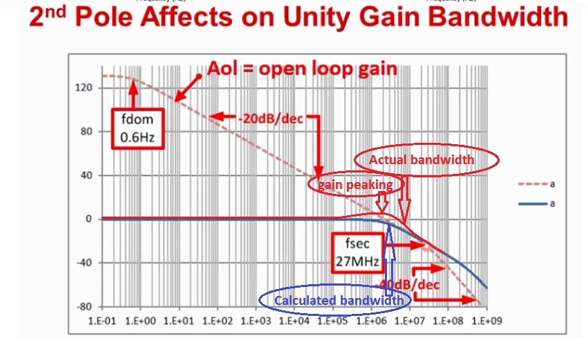
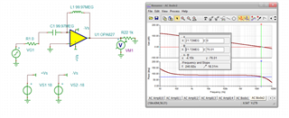
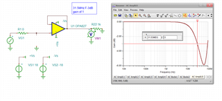
For calculation, the bandwidth is 11MHZ. For simulation, it is 18MHZ. 

I want to confirm I use 11MHZ or 18MHZ as the bandwidth when I design the circuit? Which is correct?  Why?

If use 18MHZ as the bandwidth when I design the circuit, this mean I need to simulate to confirm the bandwidth at the first when I design the circuit?

Tengfei

  • Well Tengfei

    The gain bandwidth product idea only works (exactly) if the phase margin at LG crossover is 90deg. As the phase margin decreases, the closed loop bandwidth will be extended. If the overall loop gain is 2nd order, that extension will be predicted by Figure 4 in this article, often it is more than 2nd order so this is still approximate, 

    https://www.planetanalog.com/stability-issues-for-high-speed-amplifiers-introductory-background-and-improved-analysis-insight-5/

  • Tengfei,

    Adding to Michael's comments, the theoretical bandwidth is a function of noise gain, BW = GBW/(Non_Inv_Gain), but this work well ONLY for higher gains: for example, for G=10, BW=22MHz/10=~2.2MHz while for Gain=100, BW=22MHZ/100=~220kHz. For low gains, the input capacitance interacts with the output impedance resulting in so call gain peaking, which extends the bandwidth above the calculated value; having said that, a higher bandwidth is typically not a problem. 

  • Hi Tengfei,

    I want to confirm I use 11MHZ or 18MHZ as the bandwidth when I design the circuit? Which is correct?  Why?

    The video content section refers to Secondary Bandwidth Effects, and you should go through it over again. As Michael pointed out, the closed loop bandwidth with be extended. In other words, there are poles near the unity gain bandwidth and resulted the 2nd bandwidth effects. 

    In an open loop, there is dominated pole (fdom) as shown in the captured image below. The pole rolls off at a rate of -20dB/decade and there is no additional poles near the unity gain BW as shown in the Simplied Single Pole Model, where the phase shift in the single pole model is 90 degree. Under the specific condition, the open loop bode plot is able to predict the close loop behavior using Gain x Bandwidth Product. 

    If there are poles in the vicinity of an unity gain BW, then the Gain Bandwidth Product (GBP) is no longer applicable as the example shown in "More Comprehensive 2 Pole Model" plot and also see Michael's article. 

    In the same Precision Labs video series as shown below ( @8:44 timestamp), the presenter indicated that there are up to ±30% variations of GBP specified in a datasheet at 25C (typical). There are additional up to ±30% variations or errors over the specified temperature range. 

    https://training.ti.com/ti-precision-labs-op-amps-bandwidth-gain-gbw?context=1139747-1139745-14685-1138800-13125

    I do not have your application requirements, schematic and gain settings of your circuit, and I am unable to say weather it is 11MHz or 18MHz. One is estimated by GBP equation and other one is simulated. The video is demonstrated Secondary Bandwidth Effects when measuring unity gain BW with additional poles near the BW frequency. If you want to know what it is, you need to simulate in a Loop_Gain plot in an actual circuit and measure the unity gain BW and phase margin. Also please see the video training series below. 

    https://training.ti.com/ti-precision-labs-op-amps-stability-phase-margin?context=1139747-1139745-14685-1138805-13849

    If you have additional questions, please let us know. 

    Best,

    Raymond

  • See below graphs of Calculated (theoretical) vs Actual -3dB bandwidth for low gain configurations:

  • So I had this file already set up, a quick Aol test, with 1kohm load, 21.7MHz xover with 75deg phase margin, 

    Going into that Figure 4 exact bandwidth extension curve shows a 1.35X factor - so we should expect about 1.35*21.7Mhz = 29.3Mhz F-3dB, 

    Running that gives this, about 31.5Mhz - pretty close actually, looks like there is some feedthru at higher F. 

    using this TINA model revision, 

  • Hi Tengfei,

    the difference between 11MHz and 18MHz is not all too big. Speaking in terms of linearizing gain reserve, 18MHz would offer only 4.3dB more gain reserve than 11MHz. Compared to the gain reserve of about 40dB in a precision application, 4.3dB makes only about 10%.

    What is the gain and signal bandwidth of your OPA827 application?

    Kai

  • Also Tengfei, 

    This article came up yesterday in a different discussion, explains this in more detail with a step by step example using the OPA134 as an example device, 

    https://www.planetanalog.com/why-is-amplifier-gbp-so-confusing-insight-12/