Other Parts Discussed in Thread: LMH6624, OPA202, TINA-TI, OPA354
Hello everyone,
I am using the JFE150 transistor to develop a low noise transconductance preamplifier. The input of this circuit is an antenna made out of a parallel LC circuit. I want to measure the voltage of the LC.
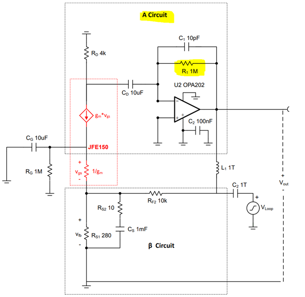
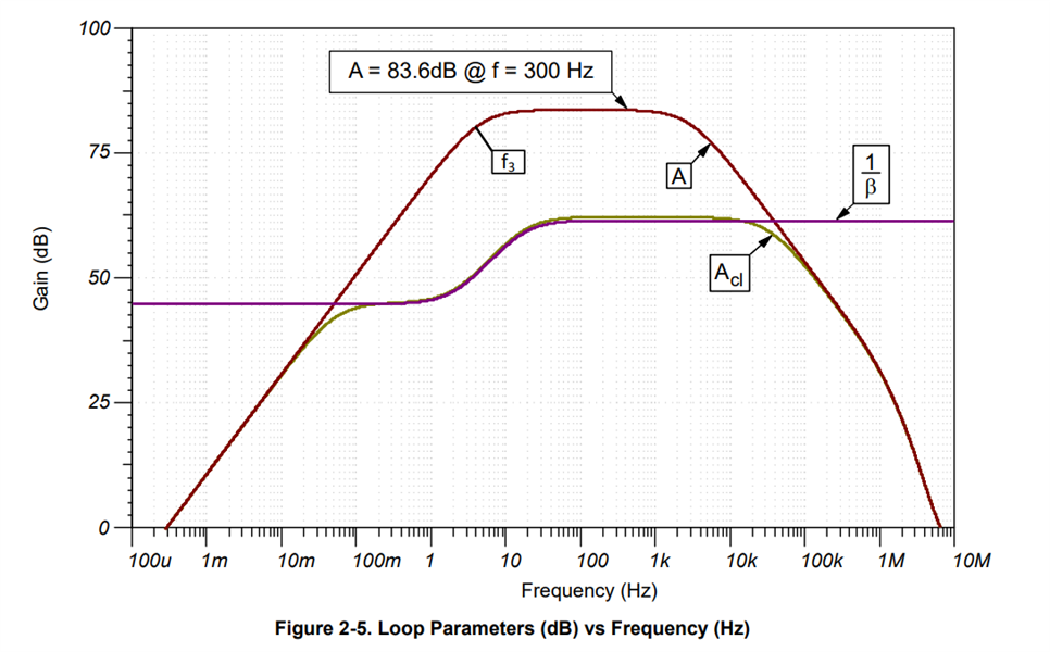
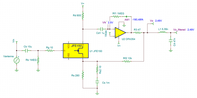
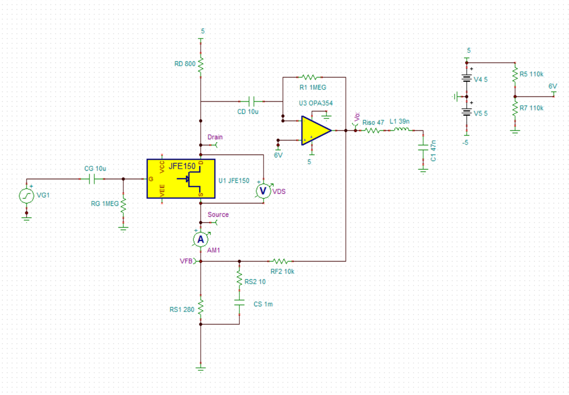
I inspired myself from the JFE150's circuit in datasheet and application note, but as my requirements are a little bit different, I changed the values of some components
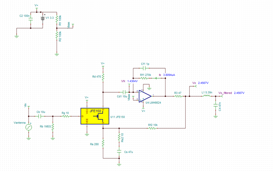
- My frequency range is hundreds of kHz so I changed the OPA202 for an LMH6624 with a bigger GBW
- I work with a single 3.3V supply and changed Rd from 4k to 470, otherwise Rd would have restricted current to drain
- I changed Cs to 47uF
- I changed the values of feedback network to increase cutoff frequency
- I put two LMH6624 in parallel to increase SNR to 3dB
- I added an LC filter at the output
We have the following schematic:
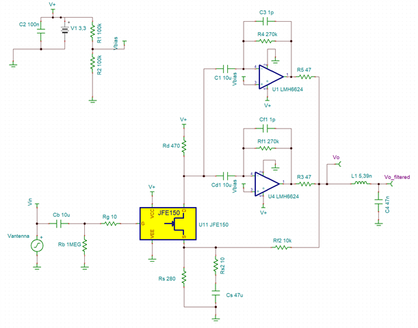
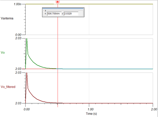
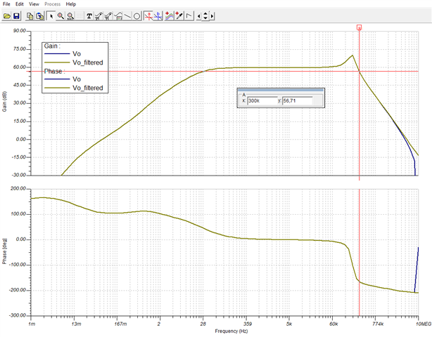
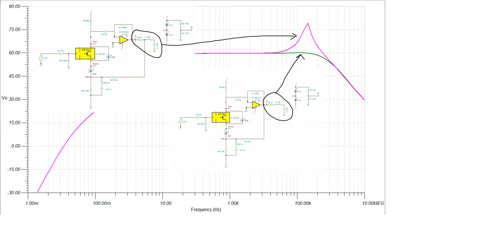
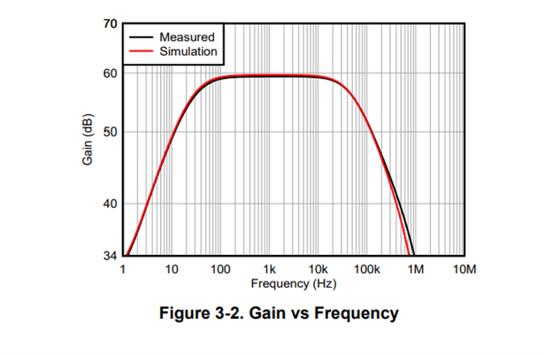
With TINA-TI, the gain is approximately 55-60 dB in my working frequency, which is very good (in simulation)
But as theory and praxis always dance together in a strange way and hide some surprises which makes our days of work sometimes very fun, I had a different behavior on my physical board.
As I put the power on, output increase slowly (approx 2-3 seconds) and stays at 2.55 volts. Voltages are:
- Vout = 2.55V
- Voltage on drain is 3.3V
- Vfb = 2.55V, like Vout
- Vbias = 1.3V
I tried the circuit with one LMH6624, then with open loop, no change. Behavior stays as described below on the oscilloscope measure:
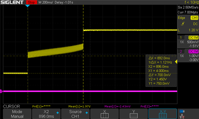
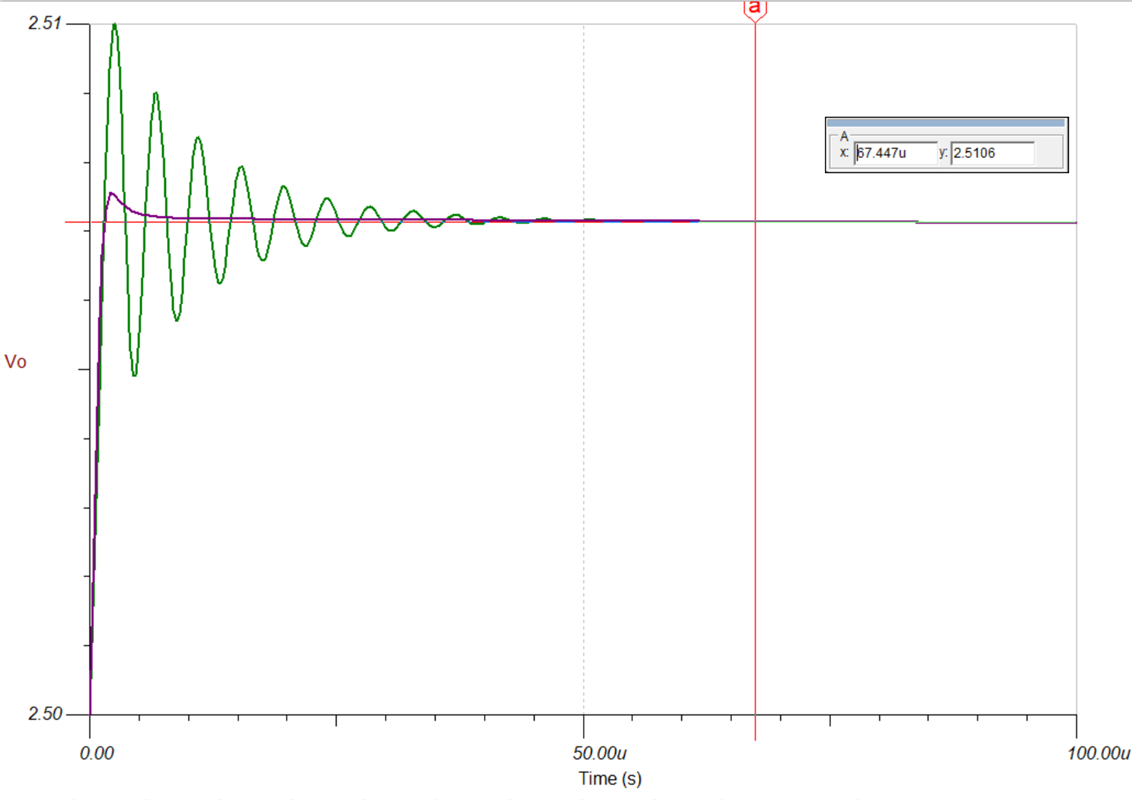
0V (gnd) is at the pink line. First there is a jump of 0.7V, then a sawtooth signal (middle part), then signal jumps again of 0.7V and stays at 2.55V.
- Does this behavior comes from the clamping diods? I connected VCH and VCL
- Should I work with dual supply (+/-) instead of single supply?
- Is there something I didn't see?
Any recommendation, help is welcome.
Thank you very much
Jeremie


