This thread has been locked.

If you have a related question, please click the "Ask a related question" button in the top right corner. The newly created question will be automatically linked to this question.

INA 821 for motor current measurement

Part Number: INA821
Other Parts Discussed in Thread: LM27761, LM2776, INA849

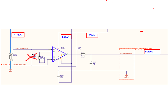
We use the INA821 in a motor current measurement application. the supply voltage is only +5 Vdc. on the REF-INPUT we have connected a reference voltage of 1,65V dc to move up the zero point to 1,65V. THat shall allow us to measure also possible negative current. A shunt resistor of 4 mOHM is connected between the differential measutrement inputs pin 1 and 4. A CURRENT is flowing through the shunt in the range from 0 to 20 A.

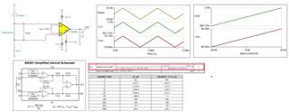
the Gain is set to G=10.  THE output of the INA 821  stays on the level of the reference voltage.  FOR a current flow of 10 A i have  expected to measure on the output of a voltage of 1,69V. BUT I measure still 1,65 V. OVER THE shunt of 4mOHM i MEASAURE A VOLTAGE OF 4 mV. BUT THIS VOLTAGE is not recogniced by the INA821. we don'Tt understand the behaviour of the ina 821.The figure below describes the circuit i have described above.
  • Hi Nobbi,

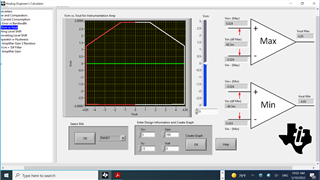
    The reason that it did not work is that INA821's Vcm is required to be ±2V from the supply rail, as shown in the simulation below. 

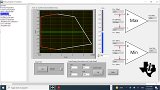
    In the simulation below, +/-5V supply rail is used. Current sensing is bidirectional and without violating Vcm input requirements. 

    FYI, the power dissipation of 4mOhm Rsense resistor may dissipate up to 1.6W_max. 

    INA821 Isense Motor 05102022.TSC

    Below is the link of analog engineer's calculator, where you may download it and check it out on your own. 

    https://www.ti.com/tool/ANALOG-ENGINEER-CALC

    Without dual supply voltage rails, the Rsense setup is required to meet Vcm requirements, and it may work as well. The Rsense is likely placed on low side in the application since the single supply rail is low voltage type.  

    If you have additional questions, please let us know. 

    Best,

    Raymond 

  • HELLO Raymond,

    thank you for the fast response. IN the mean time WE found also the reason.   IN our aplication the Rsense is in the low side path. DO you know an instrument amplifier for our aplication? WE want to supply it with only 5 Vdc. THE BANDWITH  must be high enough above 1 MHz. THE slew rate must be high  u.f.  > 2V µs. WOULD be great when you can propose an usable instrument applifier  or a current amplifier.

  • Hi Nobbi,

    WE want to supply it with only 5 Vdc. THE BANDWITH  must be high enough above 1 MHz. THE slew rate must be high  u.f.  > 2V µs. WOULD be great when you can propose an usable instrument applifier  or a current amplifier.

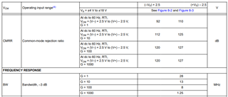
    If you are looking for high BW than INA821, then INA849 may be the option. If you are sensing on the low side, you have to use dual supply rails, where you do not violate the input Vcm requirements. I would suggest to generate the negative voltage rail with LM27761, LM266x or LM2776, where these are switched capacitor inverter or charge-pump voltage regulator. 

    https://www.ti.com/amplifier-circuit/instrumentation/products.html?keyMatch=INSTRUMENTATION%20AMPLIFIER#sort=p1181typ;desc

    Below is the capture of key specifications that you may be interested. 

    I believed that this is a motor application, Why do you need bandwidth over 1MHz? For current sensing application, your options are limited for the high frequency.

    Best,

    Raymond 

  • Hi Nobbi, 

    I hope that your issues have been resolved. 

    I am going to close this inquiry.. If you have additional questions, you are still able to open this thread or create a new one via E2E forum. 

    Best,

    Raymond