This thread has been locked.
If you have a related question, please click the "Ask a related question" button in the top right corner. The newly created question will be automatically linked to this question.
Hi Team,
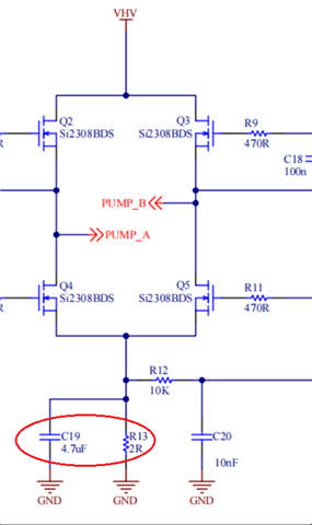
I want to measure the current through a resistor that is connected to the low side.
The Resistor R13 (2E) is the sense resistor.
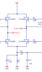
The H Bridge is switching at 22KHz.
The expected current through the sense resistor is 100mA.
So the voltage developed across the resistor will be 100mA*2E=200mV.
I need to amplify this 200mV to about a 3V range, so I need a gain of approximately 10.
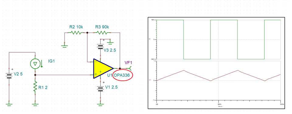
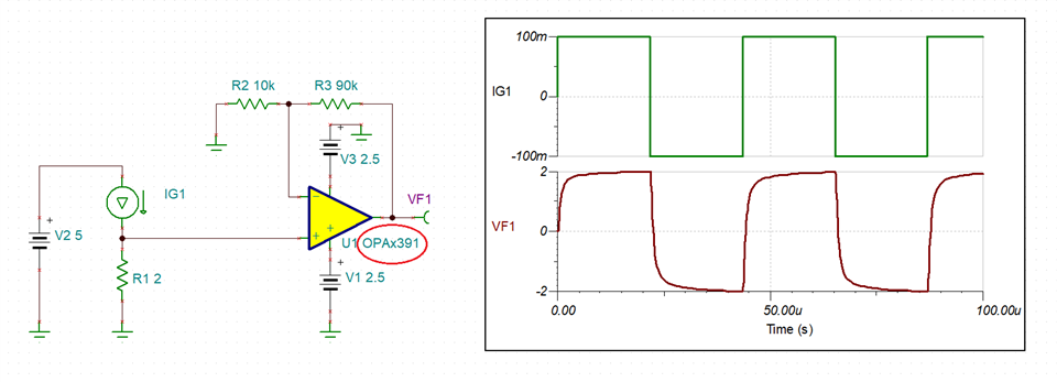
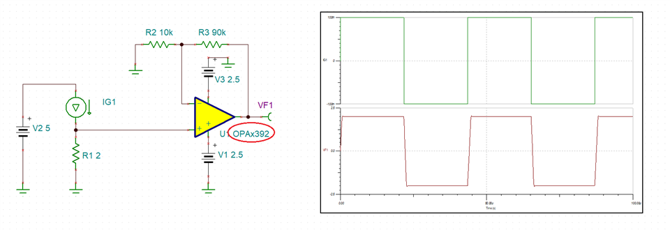
The feedback resistor of the op-amp OPA2336 is taken as 100K and the gain resistor is taken as 10.5K.
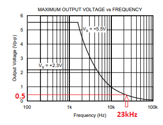
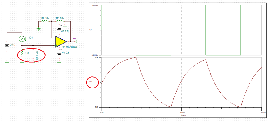
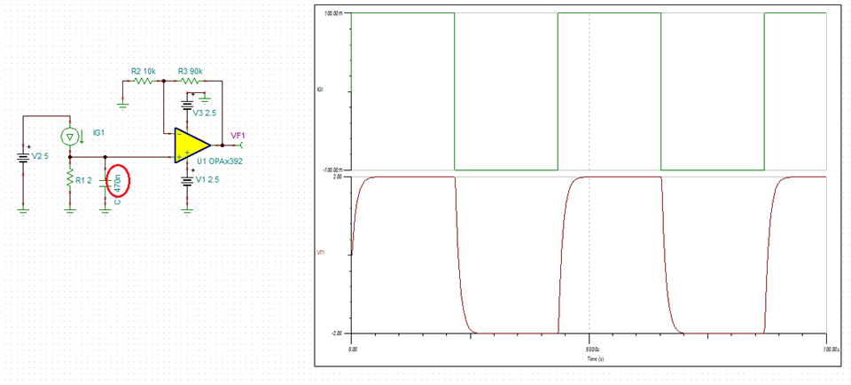
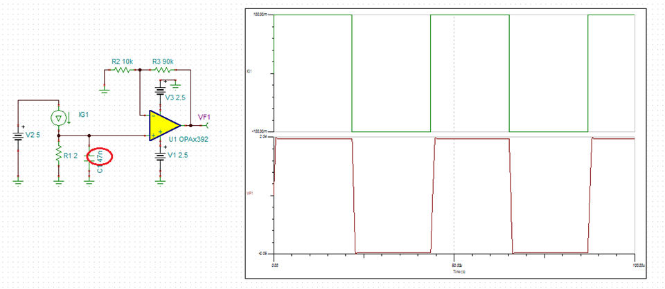
The Gain-Bandwidth Product of OPA2336 is only100KHz.
The H bridge is switching at 23kHz, since the current sensing is outside the H-bridge, the current signal is rectified to 46kHz.
Maximum amplification will be 100KHz/46KHz = 2.17
My required amplification is 11.
Is my calculation correct?. Please correct me If I am wrong.
Could you please explain the relationship between the GBWP and the maximum input frequency of an op-amp?.
Shibin,
The small signal bandwidth is a function of a close-loop Gain: BW=GBW/Gain. Thus, in Gain=10, OPA336 small-signal bandwidth is just 10kHz (100kHz/10) - please review TI precision lab training material under following link: https://training.ti.com/ti-precision-labs-op-amps-bandwidth-bode-plots-cutoff-frequency?context=1139747-1139745-14685-1138800-13124
However, even greater limitation of your application comes from OPA336 slew rate of 0.03V/us, which further limits the large signal to just 0.5V at 23kHz - this is called a full-power bandwidth and it is shown in the graph below.
Therefore, OPA336 is much too slow for what you need - see below.
Thus, you need an op amp with a higher slew rate like OPA391 (SR=1V/us) or even better OPA392 (SR=4V/us) - see below.
Having said that, the time-constant (C19||R13) is around 10us, thus in order to allow reading of 23kHz signal, you need to lower the value of C19 cap by at least 10x - see below.
Attached please find the circuit schematic you may modify to your exact application conditions.
Hello Marek,
Thank you for your reply.
We will update the design using the op amp OPA392.
How do you calculated the time constant of the combination R13||C19
Hello Marek,
Thank you for your reply.
The resistor R12 and Capacitor C20 forms an RC network. How the parallel combination of R13 amd C19 forms an RC low pass filter?
R13||C19 (or R1||C1 below) form not a low-pass filter but RC time constant that slows down the input signal - see below.
τ= 10us
τ= 1us
τ= 0.1us