


Other Parts Discussed in Thread: INA186, INA293
Hi there,
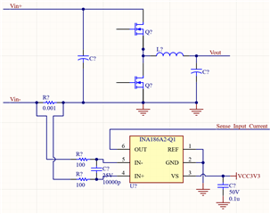
I'm looking for some guidance on selecting a current sense amplifier for measuring the input current to a Buck DCDC converter. This measurement will be used for MPPT and efficiency calculations. Here is some basic circuit info:
Vcm: 0-100V
Max current sense resistance: 1mOhm
Preferred Gain: >= 50V/V
Input Current Range: 0-50A required (0-66A allowed by 1mOhm sense resistor, G=50 current sense amp, and 3.3V reference)
AD Converter Precision: 12 bits (~16mA/bit)
AD Converter Sample Frequency: ~30kHz
DCDC Converter PWM Frequency: ~200KHz
DCDC Converter Output Voltage: ~12V
Low Side or High Side measurement is acceptable.
Here is a quick example:
I am familiar with most of what causes error in amplifiers like this (Changing Vcm, Vos, etc.), but I am struggling to determine the minimum bandwidth I need for this system. I am worried that if I pick a current sense amp with a low bandwidth (such as the INA186), it will respond too slow and won't accurately reflect the input current. The INA240 has a higher bandwidth than the INA186, but I still wonder if 400KHz is enough. The INA293 bandwidth is getting better at 1.3MHz.
This topic is discussed a little in Chapter 3 of slyy154a.pdf:
A common approach to this measurement is to select
a current-sense amplifier with a wide bandwidth. In
order to stay above the audible frequency range, the
typical modulation frequencies range from 20 kHz to
30 kHz. Amplifier selection for making in-line current
measurements in these PWM-driven applications targets
amplifiers with signal bandwidths in the
200 kHz to 500 kHz range.
This is in reference to fast changing Vcms, but I believe it is still relevant. It seems like they are recommending a bandwidth that is 10 times the PWM frequency.
The need to accurately and quickly detect the load
current through a low-side shunt resistor is a critical
application required for overcurrent protection, faster
feedback control loops, accurate battery and power supply
monitoring....
Low-side current-measurement applications traditionally
have used a dedicated current-sense amplifier, precision
amplifier or general-purpose amplifier connected to an
external sense resistor. However, in applications where
you need to detect small high-speed transient pulses,
these devices tend to lack the adequate bandwidth
needed to replicate the pulse accurately in a single gain
stage.
To further complicate this, the sample frequency is only ~30KHz (which is synced with edges of the PWM). I believe this topic boils down to the following question:
Should I come up with a high bandwidth solution so I can measure an accurate instantaneous current, or should I choose a lower bandwidth solution and let it naturally average the input current for measurement?
Any guidance would be greatly appreciated.
Thanks,
Phillip
