A related question is a question created from another question. When the related question is created, it will be automatically linked to the original question.
If you have a related question, please click the "Ask a related question" button in the top right corner. The newly created question will be automatically linked to this question.
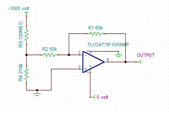
TLV2471: voltage divider problem for high voltage using opamp TLV2471
due to the finite gain of OPAmp the -input goes below 0V and leaves the allowed common mode input voltage range:
The use of a small positive pseudo ground or the use of the LM7705 at the negative supply voltage pin of OPAmp can help.
But take care, there's another issue:
If the supply voltage is down while the -1000V is already present, an even higher negative voltage will reach the input of OPAmp which can cause latch-up or lock-up during the next power-up. So, you should modify this way too simple circuit by adding a proper protection circuit at the input of OPAmp.
You might want to see a very similar discussion in this thread:
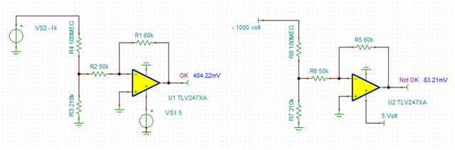
Did you connect the two voltages to voltage sources?
Is the problem was very little output voltage (83mV) then this may be the reason
If 484mV is unexpected, then consider that R4 (R3 in your schematic) and R2 effectively are in parallel for node where the three resistors meet (and the op amp is running).
Make R4 a few resistor in series to reduce the voltage across each section of R4 resistor.
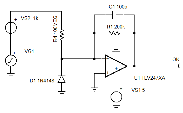
D1 is just a another voltage limiter when the op amp is off or is missing or has a (solder) continuity problem. In normal operation there will be less than 10mV across D1.
C1 limits bandwidth to 8kHz and prevents lag in the feedback (due to capacitance of input and the diode) to help loop stability