This thread has been locked.

If you have a related question, please click the "Ask a related question" button in the top right corner. The newly created question will be automatically linked to this question.

JFE2140: Input bias currents with JFE2140 SPICE model

Part Number: JFE2140
Other Parts Discussed in Thread: TINA-TI

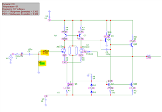
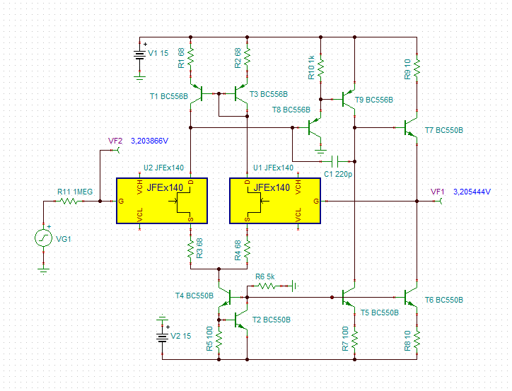
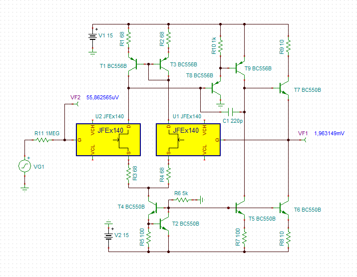
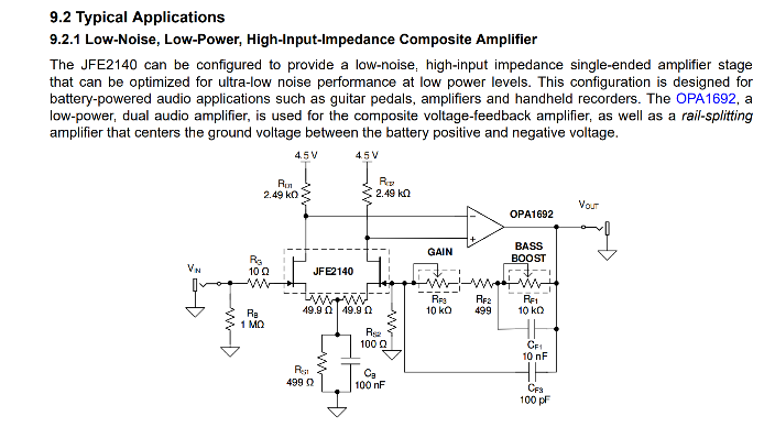
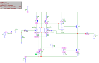
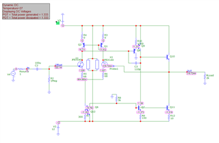
I'm working on a discrete operational amplifier for audio purposes, and the JFE2140 seemed well suited as an input stage. However, on importing the model into my preferred sim, Microcap 12, I saw atypically high input offsets.
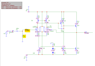
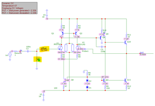
 

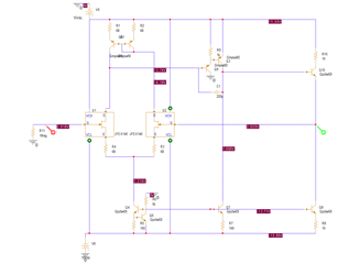
I was able to approximately replicate this behavior in PSpice for TI

and so I do not believe it reflects an error in the import or simulation software.

Changing the integrated diode Rs
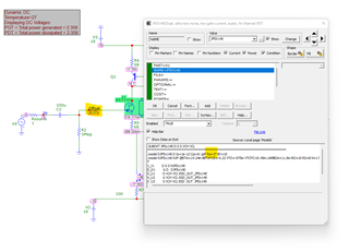
and breakdown voltage
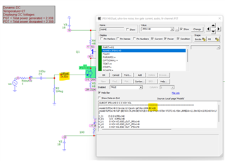
both appear to restore correctish behavior per the datasheet - is it possible to check if the values in the current .lib are correct?

I will note that this fix works even with the diodes floated, and floating the diodes does not seem to impact the offset behavior in SPICE in my testing.

  • Hi Blaine,

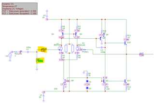
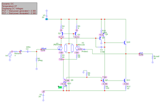
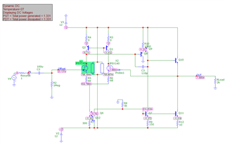
    I get similar results in TINA-TI.

    For BV=10:

    And for BV=40:

    blaine_jfe140.TSC

    Kai

  • Hi Kai,

    Thanks for replicating in Tina!

    It seems like that or another parameter must be incorrect, given that I can't imagine that the datasheet implementation is intended to have over 2V of output offset

  • Blaine, 

    I am currently looking into this with our model expert. I will update you with our findings within the next two days. 

    Best Regards, 

    Chris Featherstone

  • Blaine,

    What you are observing is the behavioral modeled current as shown below:

    The current times the 1Mohm resistor on the left side is giving the large offset values. The model values are correctly applied to model this behavior. 

    Best Regards, 

    Chris Featherstone

  • Hi Chris,

    I may be misunderstanding you here, but I'm not certain I get why, if this is the case, changing the diode breakdown voltage changes the behavior - as said, even with the transistor model unchanged, this radically changes the input bias.

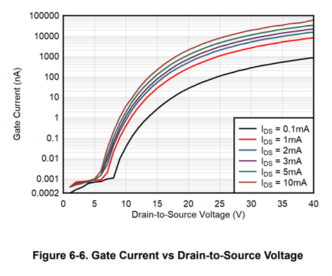
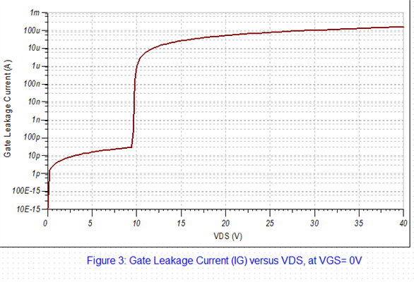
    I'm also not sure that the math quite adds up - in this model, with 1mA Ids and approximately 11Vds, we see an offset of 6.979V/1Meg = 6979nA. Unless I misread this plot, we would be expecting a gate current closer to 1-10nA in this range.

    The input bias also doesn't appear to vary as per that plot with the model - halving the rail voltage (which doesn't halve the Vds unless I'm missing something) drops the input offset voltage to under 20uV

    while raising it to 12 per side instantly raises it to the mV range

    Which raising the diode breakdown voltage to 12V drops back to the uV range

    If the model behavior is correct, then I suppose the JFE2140 isn't suitable for my design, but in that case the diodes specifically appear to be limiting its usefulness to low voltage designs - again, unless I am misinterpreting here.

  • Blaine, 

    The input offset voltage is not modeled. We released one model that can be used in many various configurations as opposed to a model that was in a diff pair config that would model the input offset voltage. Each will have identical Vgs in Tina. 

    The diode in the model is modeling Figure 6-6 which is the IG leakage after 10V for JFE2140 device. This model is intended to show the usability of the device up to 10V only due to limitations in the tool and modeling Figure 6-6. The current in the simulation is much higher at 10V shown below. The measured values are what you would expect from the real device shown in Figure 6-6 above. Note that the leakage current takes off in the measured values as well, however due to limitations of spice the model does not accurately reflect the device measurements. 

    Best Regards, 

    Chris Featherstone

  • Hi Chris,

    so what is to do to make the simulation give plausible results? Increasing BV to BV=40?

    Kai

  • Kai,

    I have run this by our modelling engineer and he is currently looking into other ways he can model Figure 6-6 more realistically past 10V for Vds. 

    Best Regards, 

    Chris Featherstone