This thread has been locked.

If you have a related question, please click the "Ask a related question" button in the top right corner. The newly created question will be automatically linked to this question.

INA226: the timing when the alert pin asserts

Part Number: INA226
Other Parts Discussed in Thread: INA233

Hi team

Customer has several questions about INA226.

1. They understand they can adjsut # of averaging & the conversion time.  And the data can be updated every 4.7msec like the example of 7.4.1 Averaging and Conversion Time Considerations.

However, regarding Alert pin, does this mean that Alert pin can assert every 4.7msec or every conversion time? They are not sure yet when the device compare the data and the threshold, then the Alert pin asserts.

2. In triggered mode, they understand the conversion will start after they write anything to the Configuration Register (00h) and they can get the conversion result after the time that can be based on # of averaging & the conversion time. However, they have concerns that there can be any delays between the start conversion and writting anything to the configuration register. Do you think the device has any delays?

3. In continuous mode, they can get the conversion result every certain time that is based on # of averaging & the conversion time. Is this correct? In the example of 7.4.1, they can get the result ever 4.7msec? 

4. Regarding CVRF(Conversion Ready Flag), the understanding as below is correct?
The bit turns to "1" when the data is ready. And the bit turns to be "0" automatically after the data is read. And the bit remains "0" while the coversion is not completead. 

Regards,

Noriyuki Takahashi

  • Hey Noriyuki,

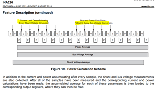
    1. The device compares the measurement with the Alert threshold after every conversion time, regardless if the number of averages. See the following images from the datasheet

    2. The device should not have any delays. Once a triggered read is initiated, the device will continue and finish the single trigger measurements (and update registers) regardless of what is written to the configuration register during the measurement acquisition.

    3. Yes. In continuous mode, the measurement registers are updated periodically according to conversion time, number averages, and mode (shunt only, bus only, or shunt and bus).  For shunt and bus continuous mode, this data refresh period = N*tconv_shunt + N*tconv_bus, where tconv = the conversion time for specific value and N = number of averages. It is important to note that the conversion times are typical and could vary +/-10%, thus the overall refresh rate can vary accordingly.

    4. Actually that is partially incorrect. The CVRF bit only clears when writing to the Configuration Register or reading from the Mask/Enable register. Note that CVRF flag is only really practical to use when using the device in its triggered mode (single-shot).

    Hope this helps.

    Sincerely,

    Peter

  • Peter, 

    Thanks for explanation.

    There are additional questions.

    1. The device compares the measurement with the Alert threshold after every conversion time, regardless if the number of averages. See the following images from the datasheet

    1. Are there anyways to make the deivce compare the threshold with the averaged value?

    2. What is the architeture of the ADC integrated in the device? 
    The ADC converts the instantaneous value of signal like SAR ADC?

    Regards,

    Norihyuki Takahashi

  • Hey Noriyuki,

    1. No. The device was intentionally designed to check for Alert threshold after every conversion to increase the speed of an over-limit condition detection. I assume customer wants to reduce the chance of a false-positive Alert detections due to current/VBUS noise, correct? There are two ways to do this. One is to increase the conversion time (tconv). Increasing tconv, makes every single measurement less noisy and is essentially an analog method to average the signal within the ADC. See Figure 20 from datasheet snippet below.

    The second method to reducing false-positive Alert detections is to use a differential input filter (Figure 21 of datasheet). This will provide analog filtering for the shunt signal and can attenuate any large current transients, thus preventing false-positive shunt over/under voltage events. If the engineer is trying to avoid, false-positive bus over/under voltage events, then use the same filter, but with capacitors from VBUS pin to GND. As explained in datasheet avoid using input resistors > 10-Ω, or else this will load down INA226 input and begin to cause noticeable gain/offset errors.

    2. The internal ADC is delta-sigma with 500kHz (+/-20%) as explained in the datasheet (see image below).

    Overall, whether to increase # averages or tconv is dependent upon system BW requirements and how system mitigates false positive (if signals are noisy). If there is enough space and BOM budget, I usually recommend using the input filter with fc > required system BW. Doing this will prevent the INA226 from needing excessive averages/tconv to smooth out signal and/or prevent false positive. If noise is not attenuated enough with input filter and there are still chances for false positive, then maximize tconv (and minimize #averages). 

    Another way to prevent false positive Alerts is through system processor/MCU firmware. You can program the ALERT functionality to transparent mode (bit 0 of register 06h). In transparent mode, if the over-limit detection only lasts for one conversion time (so if it is transient and goes away quickly), then the ALERT pin will go back to its non-active state. So you could program your processor to only shut system down only if the ALERT pin is active for several conversion times. If ALERT clears before this, then system can disregard this ALERT as a false-positive.

    Sincerely,

    Peter

  • Peter,

    Thanks. One more question.

    Can they get same converstion result at the below condtion, if they applied same input votage to VBUS pin - GND pin and VIN+ pin - VIN- pin?

    Number of average: 128

    Bus Voltage Conversion Time: 8.244ms

    Shunt Voltage Conversion Time: 8.244ms

    Regards,

    Noriyuki Takahashi

  • Hey Noriyuki,

    I am not sure I understand the question. I guess it depends on what this voltage is. Keep in mind that the input shunt voltage full scale range for INA226 is +/-81.92mV. So if VBUS=12V and they apply 12V between VIN+ and VIN-, then Vshunt will be saturated at 163.8mV. And device will report this measurement according to whatever settings you have programmed the ADC.

    I recommended maximizing tconv and minimizing number of averages in order to have a cleaner signal that is used to compare with threshold and prevent false Alert positives, all while maintaining the same data throughput the designer wants.

    If customer maximizes conversion time and number of averages (8.244ms tconv with 128 averages), then they will still reduce chances of a false positive, but the data throughput (system BW) will dramatically decrease. For the last suggest settings, the data throughput = 128*8.244ms =1.055232 seconds. It would take this time to get one measurement. Since you are also reading Vbus and Vshunt, the registers would not be updated with a new value in double this time so 2.110464 seconds.

    Hope this helps.

    Best,

    Peter

  • Hi Peter,

    Thanks. They have addtional questions.

    They try to use either INA226 or INA233 as multi-sourced devices in order to deal with the supply shortage.  So their questions are related to the differences between INA226 and INA233.

    1. Regarding In case of INA226, the device compares the measurement with the Alert threshold after every conversion time, regardless if the number of averages. But how about INA233? 
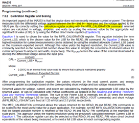
    Looking at the datasheet of INA233 as below, it seems that INA233 compare the value after every conversion + average.

    2. In case of INA226, the current register is calculated as below equation, but they can't see similar equation in the INA233 datasheet. Can this equation be applied to INA233?


    Regards,

    Noriyuki Takahashi

  • Hey Noriyuki,

    The INA233 compare the the shunt measurement with the ALERT threshold after every conversion, regardless of averaging, thus the INA233 behaves the same way as INA226 in this respect. See excerpt from INA233 datasheet below.

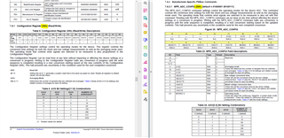
    The INA233 does have a different register map. See comparison below.

    The INA233 does have a calibration register that needs to be programmed using the same equation as needed for INA226. They both have the same Vshunt, Vbus, and power LSB values.

    Here is a comparison of the configuration register between INA226 and INA233. While the address location of the registers is different between the two devices (since they have different register maps), the actual breakdown of the register is the same.

    Both devices are I2C compatible; however, INA233 has a different register map to allow for PMBus interface compatibility. The calibration register for the devices require same equation and are programmed the same way. 

    Sincerely,

    Peter