This thread has been locked.

If you have a related question, please click the "Ask a related question" button in the top right corner. The newly created question will be automatically linked to this question.

XTR117: MSP430 and XTR117

Part Number: XTR117
Other Parts Discussed in Thread: XTR115, XTR116, XTR111

Hi, 

We are working on one 2 wire transmitter application where we have to use XTR117 and MSP430 microcontrollers. 

Also, it should have a segmented LCD and ultra-low power EEPROM. 

I am curious to know how should i connect 5V of XTR117 to the MSP430 microcontroller. 

Any application note/part number of components with reference to this will be helpful to start with circuit design.

Thanks,

Purushottam 

  • Hi,

    have you seen figure 4 and 5 of datasheet of XTR117? And read the section "MINIMUM OUTPUT CURRENT".

    Kai

  • Hi Purushottam,

    I am curious to know how should i connect 5V of XTR117 to the MSP430 microcontroller. 

    Please see the Kai's comments.  

    Below is the input voltage range of XTR117, 2-wire current loop transmitter. 5Vdc output regulated by XTR117 is unable to drive MSP430 MCU due to maximum current limitation. The 5Vdc from XTR117 is designed to drive certain low power and low current sensing application, and the 5Vreg is referenced to Iret or pin3. In other words, 5Vreg is a floating 5V reference voltage in 2-wire XTR115/XTR116/XTR117 4-20mA current loop transmitter. 

    For more information, please see the links below, where there are tons of information about the topics. 

    https://e2e.ti.com/support/amplifiers-group/amplifiers/f/amplifiers-forum/945188/faq-designing-with-4-20ma-current-loop-transmitters-xtrs-faq-links

    If you have additional questions, please let us know. 

    Best,

    Raymond

  • Hi Raymond, 

    Thanks for your advice. We have designed one application with XTR115 and Atmega169 microcontroller. Here microcontroller is driven by 5V DC from XTR115. This application is working fine. 

    It has a sensor signal conditioning circuit with an LP324DR op amp and also a segmented LCD. With all these components the current requirement of the circuit is reached at 3.7mA approximately. 

    Now we have to add one more chip of external EEPROM which will add up some more current. Hence we are thinking to use MSP 430 microcontroller to minimize current requirements. 

    As the MSP430 microcontroller has an operating voltage of up to 3.6V, I am not sure how we connect 5VDC voltage from either XTR115/XTR117 to MSP 430.  

    Any suggestions on this will help to take this ahead. 

    2_Wire_Tx.pdf

  • Hi Kai, 

    Yes, I have gone through the schematics and current details. XTR117 can supply a maximum of 25mA of current to drive other circuitry. In that case on a 2 wire transmitter, the current consumption should be less than 4mA. 

    We have to design 2 wire transmitter applications with HART compatibility. Hence I am looking for some suggestions to proceed in the right direction. 

    Thanks,

    Purushottam 

  • Hi,

    We are working on one 2 wire transmitter application where we have to use XTR117 and MSP430 microcontrollers. 

    Also, it should have a segmented LCD and ultra-low power EEPROM. 

    I am curious to know how should i connect 5V of XTR117 to the MSP430 microcontroller. 

    What is the total current consumption? Any measurements?

    As the MSP430 microcontroller has an operating voltage of up to 3.6V, I am not sure how we connect 5VDC voltage from either XTR115/XTR117 to MSP 430.  

    You could try to take a voltage regulator with a low supply current. Or put some diodes or a LED in series with the supply voltage line of µC circuitry. Or a RC filter with a sufficient R.

    Kai

  • Hello Kai,

    We have designed one application with XTR115 and Atmega169 microcontroller. Here microcontroller is driven by 5V DC from XTR115. This application is working fine. Please refer attached PDF for schematic details. 

    It has a sensor signal conditioning circuit with an LP324DR op-amp and also a segmented LCD. With all these components the current requirement of the circuit is reached at 3.7mA approximately. 

    Now we have to add one more chip of external EEPROM which will add up some more current. Hence we are thinking to use MSP 430 microcontroller to minimize current requirements. 

    For op-amp, we have the LTC2065 part from Analog Devices which can reduce the current requirement further. 

    5224.2_Wire_Tx.pdf

  • Hi Purushottam,

    Here microcontroller is driven by 5V DC from XTR115. This application is working fine. 

    By design, XTR115's power delivery in Vreg and Vref pins are designed as follows.  

    Vreg: 5Vdc * 4mA (max) = 20mW

    Vref: 2.5Vdc* 2.5mA (typical) = 6.25 mW

    Since the Vref pin is unused, the XTR115 should be able to source approx. 20mW range (maximum) from Vreg pins. 

    Technically, these pins may source more power than 20mW, then the 5Vreg will droop more and XTR115's performance specification may not be guaranteed.  

    I looked over Atmega169 microcontroller's datasheet, it is not clear how much current is being consumed etc., especially when more digital interfaces are being interfaced So I am unable to comment on these. You have to measure the current consumption and make sure that it will not exceed the datasheet's requirements.   

    Regarding to 2-wire XTR115 current loop transmitter, I have following questions. 

    1. What is PWM to 4-20mA relationships? XTR115 is V-to-I converter. XTR115 is analog linear circuit and what is the PWM at TP1 is defined. 

    2. XTR115 is 2-wire transmitter and it is only allowing one reference ground. Vreg or Vref pins are referenced to Iret pins and typically both pins are floating, and GND is on the 24V V_loop side. There are two ground nodes in your schematic and this will not work for V-to-I 4-20 mA conversion. 

    If you want to have multiple grounds, I would suggest to use XTR111 3-wire 4-20mA current loop transmitter. XTR115/XTR116/XTR117 ICs have stringent input requirements for 4-20mA current conversion. 

    Please watch the links (posted in the previous reply) about the differences between 2-wire vs. 3-wire 4-20mA current loop transmitters. 

    Best,

    Raymond

  • Hi Raymond, 

    1. What is PWM to 4-20mA relationships? XTR115 is V-to-I converter. XTR115 is analog linear circuit and what is the PWM at TP1 is defined. 

    Yes XTR115 is V to I converter and we are generating corresponding voltage signals from PWM and resistor and capacitor combination. We have adopted this method to save on additional DAC chips for voltage generation. PWM TP1 is the test point ( PWM counts are adjusted in the microcontroller to adjust 4 and 20mA current output)

    XTR115 is 2-wire transmitter and it is only allowing one reference ground. Vreg or Vref pins are referenced to Iret pins and typically both pins are floating, and GND is on the 24V V_loop side. There are two ground nodes in your schematic and this will not work for V-to-I 4-20 mA conversion.

    There are two grounds in the schematic which are shorted together through inductor L2. We have separated Analog and Digital grounds and connected at one single point. 

    So in the end, both the grounds are connected to the IRET pin only. 

    We have another product in a 3 wire application where we have used XTR111. But this is specifically 2 wire application. 

    To start with I wanted to know the interface of the 5V VREG supply to the 3.6V supply of the MSP 430 microcontroller. Meanwhile using a low operating current LDO is a good option?  

    LDO will drop the 5V supply voltage to 3.6V for the microcontroller with a very low operating current (maybe 1uA or so) and the rest other components will be on 5V. 

    Thanks,

    Purushottam 

  • Hi Purushottam,

    Ok, I think that I understood what you are trying to do. You are generating PWM signals from MSP430 MCU, pass the PWM signals (varying the duty cyles) through LPF and generating average input voltage from 0-3.3V, which it will be used as the input to the XTR115's V-to-I 4-20mA current loop conversion. 

    To start with I wanted to know the interface of the 5V VREG supply to the 3.6V supply of the MSP 430 microcontroller. Meanwhile using a low operating current LDO is a good option?  

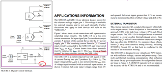
    When using 2-wire XTR115 transmitter, the input reference ground has very stringent  requirements. Since the MCU can drive with very low power, 5Vreg or Vref all may be used as supply reference for the application. However, MSP430 has to be driven in a "floating" manner as shown in the datasheet below. 

    To use a low power LDO that regulates from 5Vdc to 3.6Vdc may be an option. You may also use an op amp as voltage reference to drive the MCU, as shown in the simulation below. However, the MSP430's input pin can not have much capacitance or this driving approach will not work or will require further compensation. It is your choice.  

    Note: if LDO regulator is used, it has to be low power type. Please make sure Iq of the LDO is operating below 2-3mA range. Or the 3.6Vdc LDO has to be regulated from V+ or pin7 of the XTR115.  

    Enclosed is a simulation per your application description. 

    XTR115 05092022.TSC

    If you do not prefer the input restriction, I would recommend to use XTR111 for the input front. Please watch the following videos, which I have mentioned the links in the prior reply. 

    If you have additional questions, please let me know. 

    Best,

    Raymond

  • Hi Purushottam,

    I am going to close this inquiry. 

    If you have additional questions, please let us know. 

    Best,

    Raymond