This thread has been locked.

If you have a related question, please click the "Ask a related question" button in the top right corner. The newly created question will be automatically linked to this question.

THS3491: Frequency response of the Spice model.

Part Number: THS3491
Other Parts Discussed in Thread: TINA-TI,

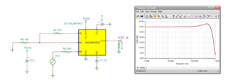
We are currently using the Spice model (THS3491RGT TINA-TI Spice Model) provided by your website for simulation in circuit design using LTSpice.
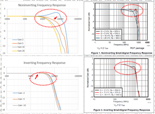
For comparison with Figures 1 and 3 in the datasheet, simple non-inverting and inverting circuits were created.

And it was confirmed that the inverting circuit shows good flatness characteristics different from the datasheet at 100 MHz and above, but the non-inverting circuit has poor flatness characteristics from 100 MHz even at 5 V/V. 
I would appreciate if you could give me some hints on this point.

  • Hi Kazuki,

    please post your results and the zipped LTSpice simulation files.

    The reason for the discrepancy is that the real circuit from which the frequency plots were taken contain real world components with some pad-to-pad capacitance and with copper traces showing some stray capacitance to signal ground. When you add these small capacitances which range from about 0.01pF to 0.2pF in the simulation much of the ripple will disappear.

    This underlines how important it is to not trust a simple simulation all too much. When it comes to HF circuits the layout plays a major role and must be taken into consideration. So, always carry out real world measurements in the developing phase with your concrete printed circuit board and be prepared that you may modify your layout a bit. This is the usual way how a HF circuit is developed.

    Kai

  • So Kasuki, 

    Here I modified the online RGT reference design (got rid of that odd Vmid stuff) - is this what you mean by not flat? This can be tuned in flat easily if you would like, 

    THS3491RGT reference design.TSC

  • Hi Kazuki-san,

    Please see Kai's and Michael's comments, and do post a screenshot of your schematic when you have a moment.

    Best,

    Sam

  • Thank you for your response.

    If it is due to parasitic capacitance, should I assume that the non-inverting amplifier circuit in the attached figure deviates from the datasheet even more at 100MHz or higher?

    Of course, I plan to verify the circuit by making a prototype on an actual printed circuit board.

    Attached are the results of my Spice analysis. Please check it out.Question_THS3491_LTSpice.zip

  • Thank you for your response.

    I am sorry, but please tell me. When you say "remove the vmid" is that synonymous with removing the following sentence in the .lib file?

    ”.PARAM VMID_DATASHEET = {(VCC_DATASHEET + VEE_DATASHEET)/2}"

  • I was just looking at the TINA reference design that has that Vmid generator to operate on any combination of supply voltages, I got rid of that and just operated split supply, in TINA. 

  • One of the mismatches between measured datasheet plots and sim plots is the bench results are operating at some voltage swing on the network analyzer. At very high frequencies, some small slew limiting effects might be in the measured data. The Inverting does work better as you are you bypassing the open loop input buffer between the two inputs. 

  • Hi Kazuki,

    I think there's a fundamental misunderstanding when discussing the bandwidth of HF-OPAmps. If you have a 10MHz OPAmp you will never use this OPAmp at signal frequencies at 10MHz or slightly below. You would use it at way lower frequencies and use the headroom of open loop gain as linearizing and stabilizing gain reserve. This gain reserve will allow you to keep temperature drifts of gain, output impedance, etc, low and especially to keep the distortion low. All this can be achieved by having a sufficiently large gain reserve.

    But when it comes to HF-OPAms many customers want to run such an OPAmp up to the -3dB bandwidth and are surprised when they see that the 3-dB bandwidth of OPAmp is so much varying with gain, capacitive loads, a.s.o. The 10MHz OPAmp will show the same fluctuations -if not way bigger- at the -3dB bandwidth. But no one would be interested in these fluctuations because all people are running this 10MHz OPAmp at way lower frequencies.

    Because of that I'm sometimes rather surprised to see what customers are expecting from HF-OPAmps.

    When it comes to the THS3491 I would never run the THS3491 at signal frequencies up to 1GHz from my experience. When looking at the figures 1...6 the frequency range between 200MHz and 1GHz appears to me to be just "gain reserve land". The frequency response is only flat up to 100MHz, maximally 200MHz. My maximum signal frequency would be 100MHz with this OPAmp.

    Or look at the distortion figures 7..17. See how the distortion "explodes" beyond 100...200MHz. Another reason to choose the maximum signal frequency at 100MHz with this OPAmp and not higher.

    Kai

  • Hi Kazuki,

    This 1.5dB peaking looks to me like a byproduct of the model, which is a best-fit macro-model using an older architecture. It seems that the model was designed to fit the G = 5V/V condition most accurately, and so the other gains (like 2V/V) are a bit unreliable. 

    Of course, the other points raised here are also excellent considerations, but I hope this satisfies your question regarding the model behavior.

    Best,
    Sam

  • Thank you for your reply and sorry for the delay in answering.
    I will try to simulate the change in Vmid with TINA.
    However, I am sorry, but I do not understand the message "The Inverting does work better as you are you bypassing the open loop input buffer between the two inputs.".
    Does it mean that the supply voltage of my model is lower than the one in the datasheet?

  • Thank you for your reply. Also, sorry for the delay in responding.
    I had not thought about the gain reserve of the OPAmp. I understood that for my application I would have to use a higher frequency OPAmp.
    In my way of thinking, this includes changing the OPAmp. Thank you very much.

  • Thank you for your reply. And sorry for the late reply.
    I understood that the model is optimized for G=5V/V only in older architectures.
    Sorry, I still have only one question. If I want to get a newer model, which model should I choose on your website? Or do you have any plan to update the model?

  • Hi Kazuki,

    We currently only have this model available for the THS3491. I will discuss prioritizing and update with the team. If you can share the circuit you are working on we may be able to help you evaluate the performance despite the model shortcomings.

    Best,

    Sam

  • The model probably does not have any shortcomings, all of these are designed to replicate the key set up for the spec lines, but also handle operating across a wide range of external conditions. For current feedback, that is just the feedback transimpedance including the inverting input effect combining with the Zol curve to give responses across gain, loading, and external R values. The model already has a lot of tuning and compromises to fit as well as possible - this is likely a perception issue. 

  • Hi Sam,

    Understood. However, I am sorry, but due to my company's confidentiality policy, I cannot release the detailed circuit immediately.
    I will email you if I hear anything else.

    Best regards.

    Kazuki

  • Hi Michael,

    I found out that I have misunderstood about HF OPAmp. Thank you very much for your detailed information.

    Best,

    Kazuki