This thread has been locked.

If you have a related question, please click the "Ask a related question" button in the top right corner. The newly created question will be automatically linked to this question.

INA163: Getting extremely hot and getting only -Vss as output

Part Number: INA163

Hello!

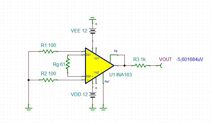
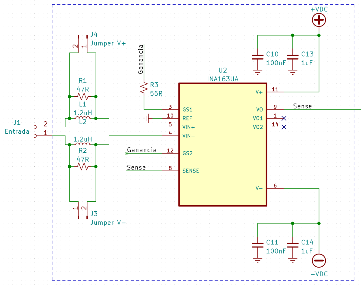
I am attempting to use an INA163 for the first stage of an electroencephalography (EEG) tool. For that purpose, this is the design I was able to come up with:

My problem: whenever I plug the power supply, the amplifier starts getting insanely hot and the output is either +VDC or -VDC, independently on the input. 

Things I tried: 

- Powering it though a bench power supply (between 9V and 12V)

- Powering it though two 12V batteries (one with reversed polarity in order to achieve the nevative voltage)

- Using the jumpers in the schematic in order to bypass the RL input circuit

- Adding a 47K resistor between input and the refference ground (as suggested in another post in order to create a path for return currents)

- Using both no load at the output as well as a resistive load

- Leaving both inputs as open circuits, shorting them together but not to ground, shorting everything to ground, changing their impedance...

I bought my IC from a well stablished seller so I am pretty sure it is not a counterfeit.

Any help will be welcome! Thank you in advance!

  • Hi Pepe,

    connect the INA163 as shown below. You should be able to measure 0V at the output. If not, then the INA163 might be damaged. Take a fresh INA163 and try again:

    Problems can arise when using a breadboard. Another cause can be noisy supply voltages. Increase the decoupling capacitances to 100µF by using aluminium electrolytic capacitors paralleled by a 100...470nF X7R each.

    Can you show a photo of your setup?

    Kai

  • Hello again and thanks for your fast reply!

    I assembled that circuit but replacing R1 and R2 with 47R resistor (I had no 100R resistors lying around, they should do the job). These are the measurements I obtain (in DC volts) in each pin: 

    1. 1.57V
    2. 0V
    3. -0.58V
    4. -0.001V
    5. -0.001V
    6. -7.01V
    7. 0V

    8. -5.54V
    9. -5.54V
    10. 0V
    11. 9.99V
    12. -0.57V
    13. 0V
    14. -5.5V

    Here there's a photo of my setup:

  • Something I just noted: if I touch the IC with something relatively cold (or at least colder than it, which is so hot), the output voltage comes back to 0V, which I assume is its normal operation

  • Hi Pepe,

    I duplicated your schematic and here the voltage nodes should be, see the image below. With 0V inputs, Vpin1 and Vpin14 should measure near ground. My guess is that the INA163 may be damaged. 

    Before you replace the INA163, please do the following. 

    1. Use a soft brush, scrub (in circular motion) and clean up the PCB with alcohol (ethanol and/or IPA) and water. Please make sure that there are no cold solder joints. 

    2. Check out the measurement again after the PCB is cleaned and dried. 

    3. If you are getting the similar result, please replace INA163. 

    INA163 06232022.TSC

    If you have additional questions, please let us know. 

    Best,

    Raymond

  • Hi Pepe,

    I fully agree with Raymond. The chip seems to be damaged.

    Please don't feel offended, but the printed circuit board looks terrible. All the cables show "cold" solder joints and the whole board seems to have seen too much heat for a too long period. All the solder joints are oxidized. L1, R1, R2 and R6 seem to have been barbecued.

    You urgently should improve the soldering quality. I recommend hot air soldering to not overheat the passive components. If you do hand soldering, on the other hand, decrease the tip temperature to 250...300°C and take a flux.

    Kai