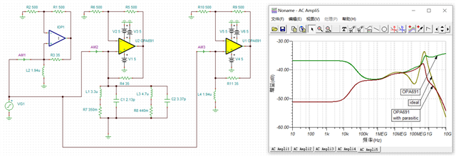
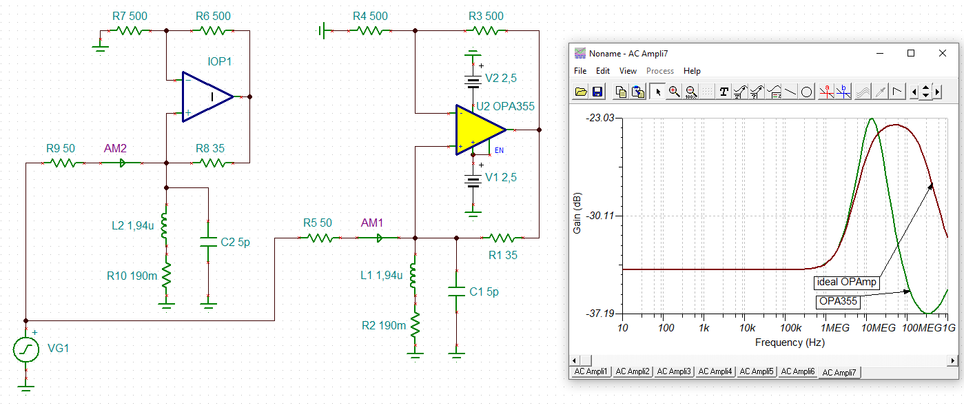
Other Parts Discussed in Thread: TINA-TI, OPA691, OPA355
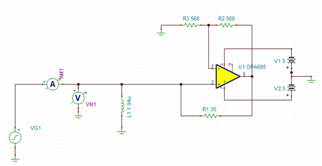
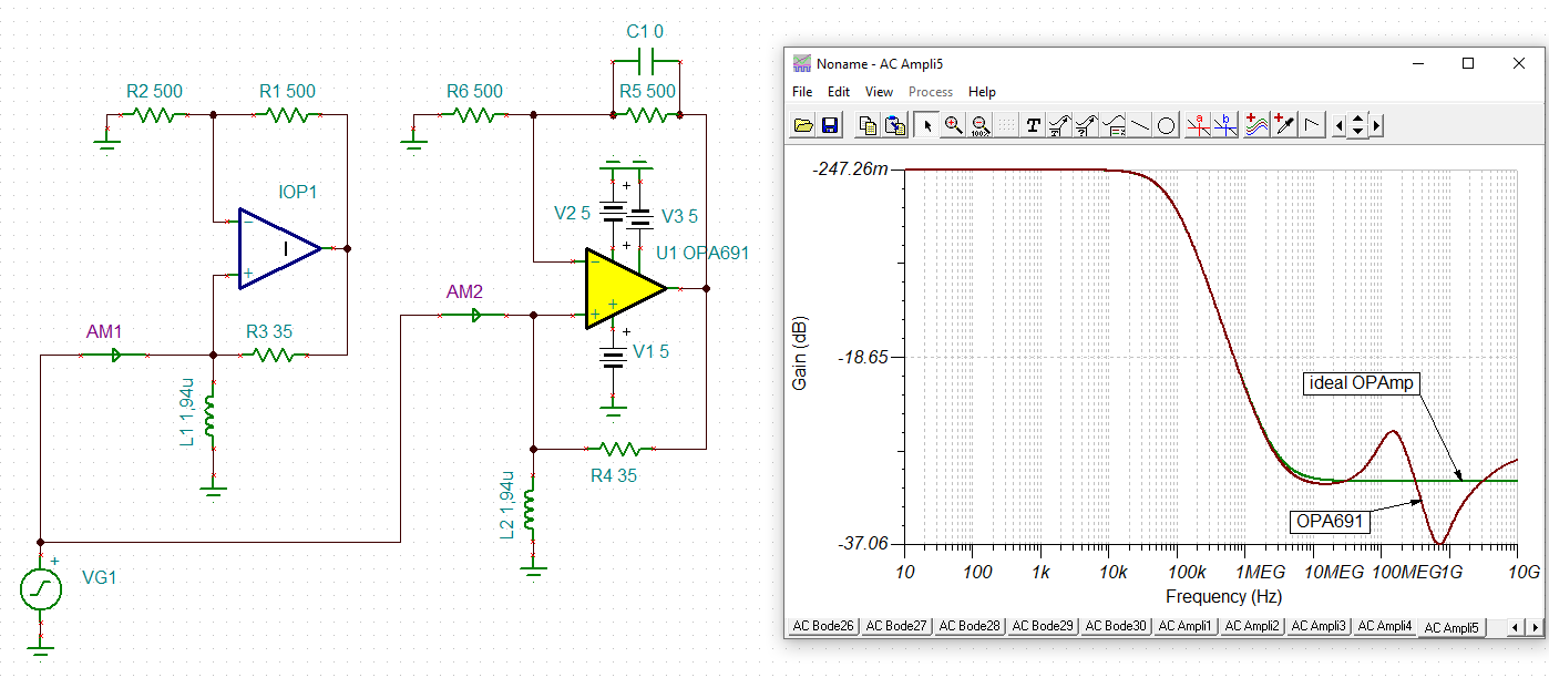
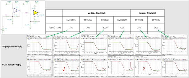
Hello, recently I'm making a negative impedance circuit with OPA695 (working frequency at 20MHz).
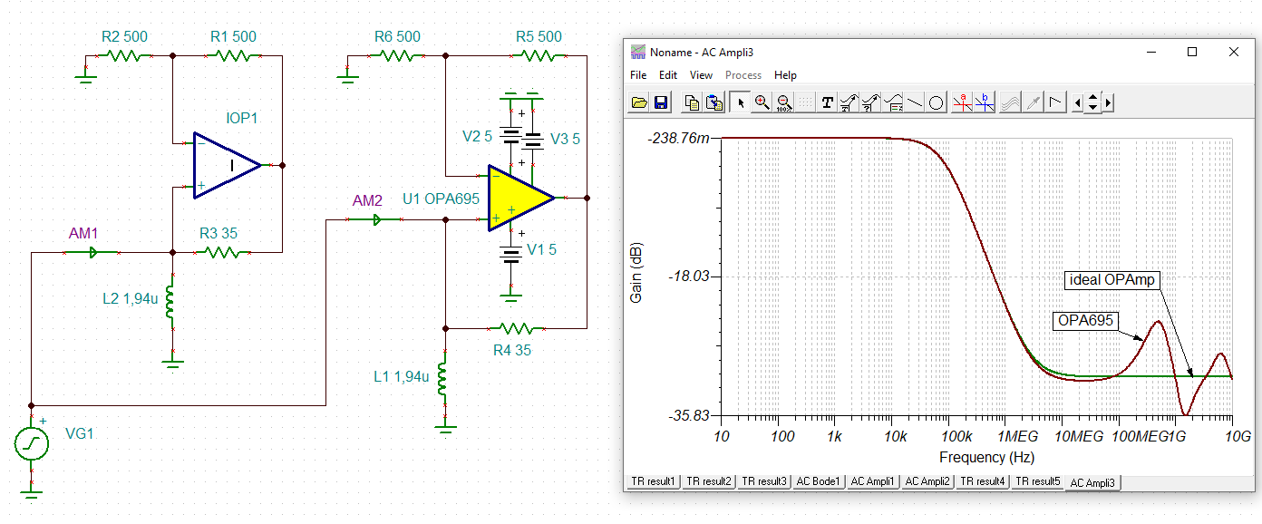
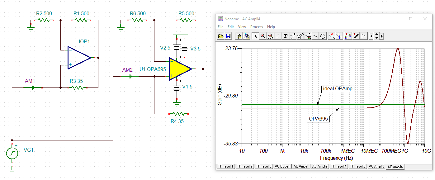
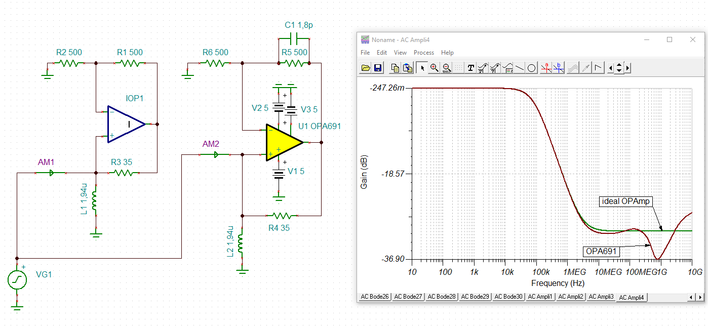
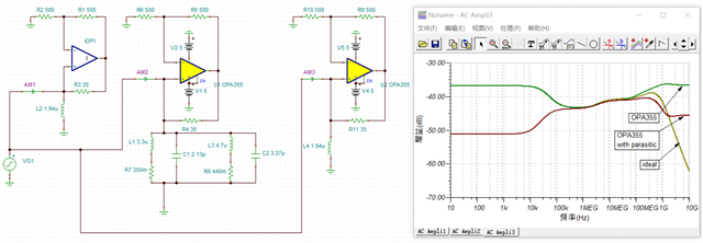
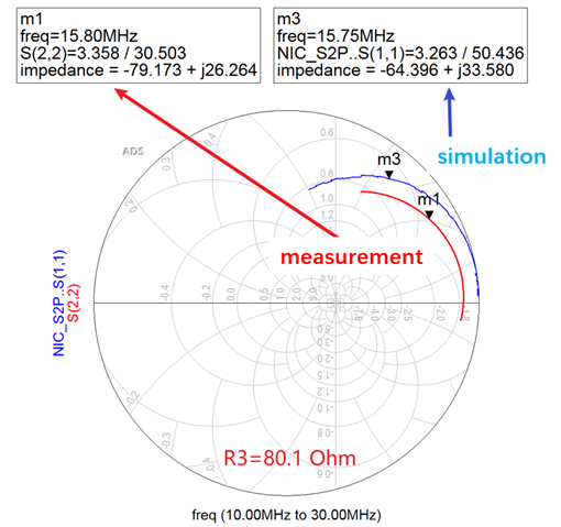
I imported the OPA695 Pspice model to the ADS 2020 update2.0 for PCB electromagnetic simulation, but I found there a big mismatch between the simulation and real measurement. Actually, the passive circuit simulation is well matched with the measurement. However, not as the amplifier circuit. I am wondering if the OP amp Pspice model is suitable for RF simulation? (But the working frequency is low enough in RF range.) Or I should choose the RF mos component which has a more accurate RF model to replace it?
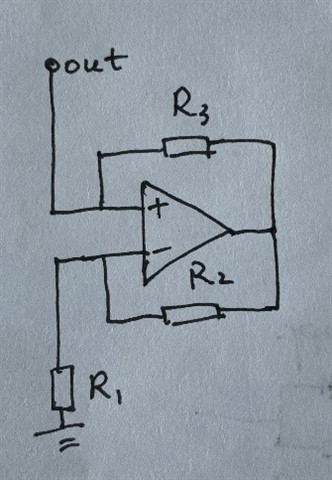
Here is the circuit schematic. R1=R2, R3 is a variable resistor (0-200 Ohm).
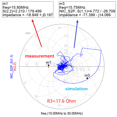
for different R3 value, the result is showing below:
(R3 is equal to 17.6 Ohm and 80.1Ohm, respectively.)
Thanks for your time!


