This thread has been locked.

If you have a related question, please click the "Ask a related question" button in the top right corner. The newly created question will be automatically linked to this question.

Problems with ISO124

Other Parts Discussed in Thread: ISO124

Hi,

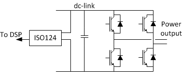
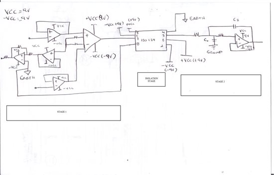
I'm working with an ISO124 device. The ISO is used for sensing a dc-link voltage (up to 600V) in a 5kW photovoltaic inverter. The schematic is as follows:

The ISO apprears to work fine, but when the IGBTs of the converter switches, then fails. In the next figure we can see the input voltage (TP63 - pink) of the ISO124 and its output (TP65 - green) when it fails. The fail is located every time at the beginning of a switching event.

I have revised the isolated power voltage (pink and blue), and it appears to be ok. See next figure:

I have changed the ISO for another new one, and it works fine for one day. Now it fails, as in the captures show below.

Thanks for the help.

  • Ivan,

    The three most likely causes of damage are:

    1. Excessive voltage transients on the power supplies on either the input or output side.

    2. Input signal voltage that exceeds the power supply voltages (positive or negative).

    3. Excessive voltage across the isolation barrier.

    You can do some simple checks for possible causes by making measurements on failed units. Measure the input side and output side quiescent currents. Are either of these currents abnormal? Measure with a ohmmeter from the input ground terminal to the output ground terminal. Use a very high resistance range on the ohmmeter. Any sign of conduction across the barrier would indicate a failed isolation barrier.

    The results of these tests will help identify the cause.

    Regards, Bruce.

  • Bruce, thanks for answering.


    I have checked this:

    The damaged ISO124 with +-15V power sources in Vs1 and Vs2. Vin = 7.5V. Decoupling capacitors of 1uF (ceramic).

    - Resistance between GND1 and GND2: Over the range of the Ohmmeter (over Gigaohms).

    - Quiescent currents:

         Ivs1+ = 5.09mA

         Ivs1- = 4.25mA

         Ivs2+ = 5.5mA

         Ivs2- = 4.97mA

    It seems to be into a normal operation range.

  • Ivan,

    From your previous description, I assume that this devices is not now functioning in any way. Is that correct?

    It appears that you timed the failure to the switching of the IGBT in your system. Can you explain what is happening in your system during this event?

    If the failure is definitely coincident with this event, there must be some sort of stress that occurs. Can you force this to occur regularly so you can look more carefully for glitches on the supplies, input or across the barrier?

    Regards, Bruce.

  • Hi Bruce,

    Again, thanks for answering.

    The device works, but randomly (coincident with a switching event) it fails, as shown in the figures of the first message in this post.

    The system is a power inverter, based on an IGBT full bridge topology. The IGBTs switches at 16kHz in order to obtain the desired output voltage. The system is as follows:

    The "ISO124 box" contains the schematic show in the first figure of the post. The fail shown occurs only in some switching events, not in all of them. Maybe in 1 of 100 switchings, randomly, but every time it occurs is coincident with a switching of one IGBT. Since this is the most noisy moment, I think that maybe can be related with noise level. When IGBTs are not switching (or switching low power) it does not occurs.

    I will post a capture of the power source of the non-isolated section as soon as I can check it in the prototype. Maybe a figure in wich appears the voltage across the barrier during this events can be interesting too.

    Thanks for the interest.


  • Ivan,

    We may have a terminology problem here.

    To me, "fail" means the device never passes a signal properly again. It's dead.

    Are you calling the event that I see in your first posting a failure? This appears to be a temporary loss of signal output that recovers in a few microseconds. Is this the problem?

    Bruce

  • Hi Bruce,

    Sorry for the terminology. What happens is a temporary loss of signal output that recovers in 20micro-seconds (aproximately). This is the problem.

  • Ivan,

    Okay. I understand. The steps in the response appear to be the internal mod/demod loop recovering from the disturbance.

    This loss of synchronization between input and output could could come from disturbance on the input, power supplies or isolation voltage across the barrier.

    The input seems to be pretty well filtered and should not have a rapid rate of change. A fast glitch on the power supplies might be a culprit. You could try much larger bypass caps--say 100uF, or so. See if it makes a difference. This might be overkill but it is a good test.

    A very rapid rate of change of voltage across the barrier can cause loss of signal. See the discussion in the data sheet on page 7--"isolation mode induced errors" and "High IMV dV/dt Errors."  If this is the problem, adding capacitance across the barrier can help. This, however, can have other risks in the application.

    Give these points some thought and measurements.

    Regards, Bruce.


  • Bruce,

    Thanks for the interest. The problem is solved.

    The power sources of the output stage where causing the problem, as it becomes very noisy when switching the IGBTs. Addint 47uF capacitors directly in the pins of the device did fixed the problem.

    Again, thanks for the help.

    Regards,

    Iván

  • HI, I NEED A HELP ABOUT ISO 124 PLEASE. Here says:http://e2e.ti.com/support/amplifiers/precision_amplifiers/f/14/t/156139.aspx#566041  

    I don't speak 100% english. I apologize if you find mistake in this. I bought iso 124 cause i need isolate 2 stage, and i am confused because i wanna use only one battery (9V=VCC) for my circuit, iso 124 requires 2, but i have questions, can i use voltage regulators for the other VCC and -VCC? or what supposed to going to do? and the battery has one ground, and i dont know if can i use that ground for stage 1 and stage 2? (Figure 1) My teacher told me with DC/DC Converser, i found MC34063A but this does not have its own ground, somebody can help me how can i use iso 124 with only one battery?

    Thank you, i hope your answer please! I need it soon.