This thread has been locked.

If you have a related question, please click the "Ask a related question" button in the top right corner. The newly created question will be automatically linked to this question.

INA226: Address error

Part Number: INA226
Other Parts Discussed in Thread: ISO1541, ISO1640, TCA9517A, TCA9800, ISO1641

Hi Team,

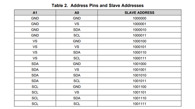
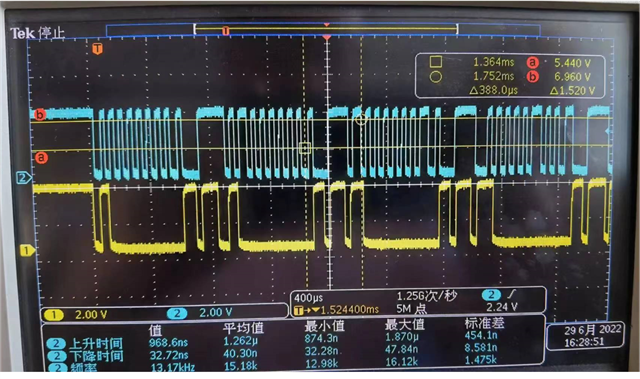
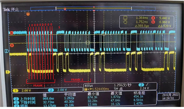
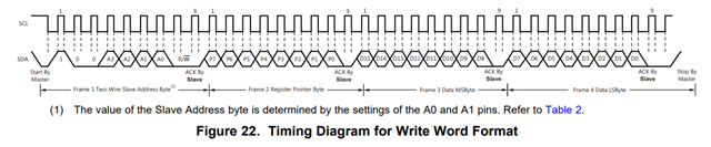
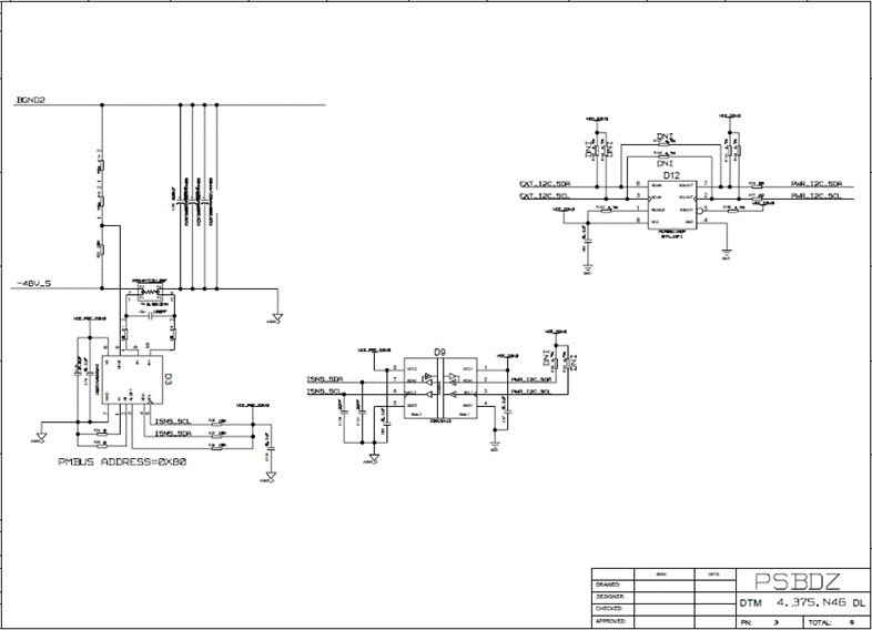
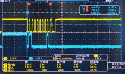
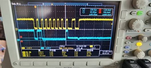
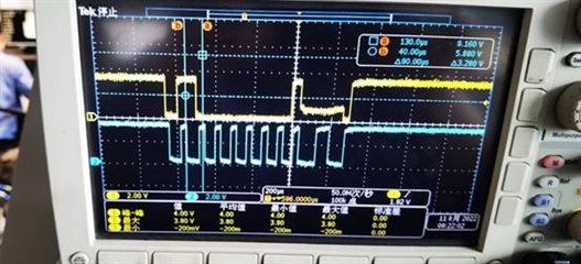
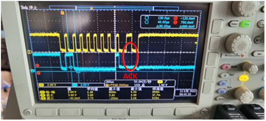
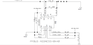
Customer used the I2C to read the data of the INA226.They used the 0X40 address to read this current, But they don't have ACK respond. I suspect that that address or format is wrong. Would you please help me to check it?

Thanks a lot.

  • Hello,

    Address 0x40 is correct for the configuration seen in your circuit. Please see table below.

    Please refer to the datasheet pages 19 and 20 for correct i2c communication with the INA226 part.

    What speed are you operating the i2c communication?

    Regards,

    Cas

  • Hi Castrense,

    Would you please help me to check the schematic? i2c communication are as follow

    Thanks a lot.

  • Hello,

    The INA226 is ack on the ninth clock pulse. Your code does not seem to be doing anything but repeating the sending of the slave address.

    So the first frame (frame 1) is the slave address being sent with a write (0 on pulse 8). The INA gives an ack (0 on pulse 9). Then you must keep I2C communication and send the register you want to write data to. See table 4 in the INA226 datasheet. The next two frames will be the data written to the register set in frame 2. After the 4th frame I2C communication can end. This is for a write to a register. 

    The start/restart should not happen between frames when trying to write to the INA. 

    Below is the timing diagram for writing to the INA226. 

    I am guessing you will also try to read from the INA226, if you have any questions about that or what is written above please reply.

    Regards,

    Cas

  • Hi,Castrense

             I am the question of this address, and now the situation is as follows: regardless of the read and write timing configuration of the subsequent data, we write 0x40 into the address. According to the oscillograph, the ninth position is low, but in fact, we print the ACK value of this block as 1, which is supposed to be just picked up the rising edge of SDL. Because our code directly reported an error in the first step, it is impossible for the problem to appear later, because we have not gone to that step. I would like to ask you that you have excluded the problem of the wrong device address in this case, and what might be the cause?

             Thanks!

  • Hello,

    I would like to better understand if the problem is the code or our device. Are there any other I2C devices on the board you can communicate to and are ACKing correctly? If so what devices are they? Are you using 7 bit addressing when communicating with the INA?

    Regards,
    Cas

  • Hi! Castrense

         I  use 7-bit address for communication , and there are other devices attached to this I2C bus,such as Flex  chip -BMR485,BMR685,they also receive the ACK signal back normally

  • Hello,

    Is it possible for you to produce a scope shot when the error appears in the code? Does your code keep trying to speak to the INA if it receives a 1 for the ACK? If the code receives a 0 for the ACK what are the next steps in the code?

    Can you replace the INA226 and see if the problem persists?

    Regards,

    Cas

  • Hello!

         A scope shot ?  When the received IACK signal is 1 during INA communication in the code, it will directly goto CLOSE_EXIT and report error until the next I2C communication. When the received ACK signal is 0, it will prove that there is a reply signal and it will start to send the register address.  After receiving ACK response, a START signal will be generated again. I2C starts the cycle of reading a byte sequence or writing a byte sequence until the completion. and When I replaced to a full machine, the problem persisted.

       Thanks!

  • Hello,

    Sorry I would like to see the INA not ACK on the oscillograph. If you can get a picture of the oscillograph when the program reads a not ACK that will determine if it is the code or the INA. You mentioned the oscillograph picture above is when the code already threw an error and the problem cannot happen again. I would like to see when the problem happens what the SDA and SCL lines are actually. 

    I will also speak to another member of the team to see if they have seen this before.

    Regards,

    Cas

  • HI! 

               The following is the problem that our company INA226 I2C communication cannot be connected:

    According to the test waveform, the I2C isolator ISO1541 output low level is high (0.75V).

    Attached is the schematic diagram of INA226 I2C interface circuit.

    1.1 The ISO1541D I2C interface is faulty

            Symptom: After the processor (Master) sends the read/write INA226 register address (0x40), the ACK signal is high: INA226 (Slave) does not respond.

    Test INA226 I2C bus clock and data bus as shown below:

    Test isolator ISO1541D SDA1/SCL1 I2C bus clock and data bus as shown in the following figure:

    Test the I2C bus Buffer PCA9511 SCLIN/SDAIN The I2C bus clock and data bus are shown in the following figure:

           According to the clock and data waveform of ISO1541D SDA1/SCL1 I2C bus, the ninth bit ACK of SDA1 is 0.7V half-high level.

    As a result, the ACK read by the processor is 1: INA226 (Slave) does not respond, and I2C communication stops.

           Carefully read ISO1541D manual found that SDA2 is "0", SDA1 because there is a diode to the ground, the output is 0.75V.This part of ISO1541D is described in the following figure.

          Due to ISO1541D, the ACK "0" output of INA226 is changed to 0.75V.0.75V is an indeterminate state for the processor,

           When the processor requires the low level to be less than 0.6V, it marks the ACK signal as "1" : INA226 (Slave) does not respond, and I2C communication stops.

  • Hello,

    I should have asked about anything else connected to the SDA/SCL lines that could hamper the communication sorry about that. I saw there is a p2p replacement in the ISO1640/1641 but they still have the diode with 0.65V will this be enough to consider a low? Is it necessary to have an isolation barrier in the i2c IC?

    Regards,

    Cas

  •      Hi!

        We must have this I2C isolation circuit device, because the grounding of the two sides is different, so is there any good solution to this problem?Iso1640/1641 Low level 0.65V is still high.

        Thanks.


  • Hello,

    I will move this thread to the team that supports the i2c isolation devices. They will be better help than I can be.

    Regards,

    Cas

  • Hi,

    From what has been discussed, I am assuming that the MCU in this system is connected to side 1 of the ISO1541. If this isn't the case, please let me know.

    As you have already mentioned in your response, the MCU will not be compatible with the ISO1541 because the low level output voltage of side 1 is greater than the low level voltage required by the MCU. To make the voltage levels of these two devices compatible with each other, we recommend connecting an I2C buffer between the ISO1541 and the MCU. The TCA9517A and the TCA9800 are both I2C buffers that we recommend using for this purpose.

    We also recommend switching from the ISO1541 to the ISO1641. The ISO1641 has a lower low level output voltage while offering reinforced isolation, and is the latest version of this device.

    Regards,

    Kenneth