This thread has been locked.

If you have a related question, please click the "Ask a related question" button in the top right corner. The newly created question will be automatically linked to this question.

AMC1302EVM: Having trouble getting accurate current measurements with a shunt resistor setup

Part Number: AMC1302EVM
Other Parts Discussed in Thread: AMC3330, AMC1302, AMC3302

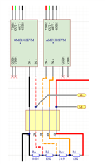
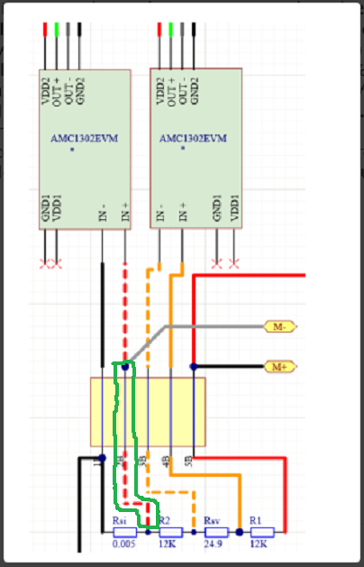
I'm using two AMC1302EVMs to characterize a DC motor. One measures the motor voltage, and one measures the motor current. I have the outputs of the amps connected to differential inputs on a DAQ module, which computes the voltage and current measurements based on the particular resistor divider network I've been using. With this setup I've been having issues with the accuracy of my current measurements. When the motor is at full speed and drawing maximum current, the measurements have an 8% relative error to the actual current the motor is drawing (confirmed using a DMM). At 25% power, they have around a 30% relative error to the actual current being drawn. Going from 25% motor power to 100% and observing the measured and actual current values, there seems to be an exponential decay relative error relationship. I have a feeling the issue is with my shunt resistor, as the value I chose is 0.005ohms. With this resistor, I first ran into issues with my wires connecting the legs of the resistor to the EVM board, as the resistance of the wires was comparable to the resistance of the shunt, resulting in a scaled version of the actual voltage getting fed into the EVM. However, even after connecting the resistor legs directly into the EVM board with no added wires, I still see this 30% -> 8% relative error trend. I imagine re-sizing my shunt resistor might help, but since the maximum input voltage range to the EVM is +/- 50mV, and my motor draws around 3A at maximum speed, the largest resistor I could use and not exceed this range is around 0.017 ohms, which is within the same order of magnitude as my original shunt. I was wondering if TI had any recommendations for how to set up a resistor divider network with a larger shunt resistor that would result in more accurate current measurements, or if there are other ways to mitigate this issue, perhaps on the EVM itself. My EVM setup diagram is included below, with Rsi being my shunt resistor used for current measurement, and M+ and M- being my motor terminals. 

  • Hi Aleks,

    the green marked connection is the problem:

    All the motor current is flowing along this connection and the unwanted voltage drop across this connection adds an offset voltage to the shunt voltage.

    Some more points:

    1. Use a four terminal shunt:

    2. Why using a voltage divider for the voltage measurement consisting of three resistors?

    3. Why not connecting the ground terminal of input voltage divider (made of two resistors) to power ground? This would improve the common mode input voltage situation for the right isolation amplifier and also help to power this isolation amplifier properly. And, by this you would get two totally separated measuring circles avoiding this unsuited "green" connection and heavily simplifying your measurement.

    Kai

  • Hi Aleks,

    Similar to Kai, I have a few concerns with your test setup. 

    I'd like to point to Figure 8-1. The AMC3302 in a Solar Inverter Application for an example block diagram. This figure shows an AMC3302 for a current measurement and an AMC3330 for a voltage measurement.  Please note that the AMC3302 is the same signal chain as the AMC1302, but features an integrated DC/DC converter, similar to the extra circuitry on the AMC1302EVM. The AMC3302 greatly simplifies the design as there is no need to establish an external high side supply. 

    For the current measurement, you can see that the shunt resistor is in series with the load and the inputs are connected across the shunt resistor. Additionally, notice that the HGND connection (GND1 on the AMC1302) is connected to the negative terminal as well to help with common-mode rejection and ensure that the inputs remain within the input common-mode range. Please make this connection in your setup. Using a 4 terminal shunt as Kai mentioned would help improve accuracy. Please refer to this Analog Engineer's circuit : https://www.ti.com/lit/an/sbaa349/sbaa349.pdf and this application note for assistance with sizing a shunt resistor: https://www.ti.com/lit/an/slyt810/slyt810.pdf

    This excel calculator can assist with estimating required shunt resistor wattage and expected current sensing device accuracy: https://www.ti.com/lit/zip/sbar020

    For the voltage measurement, there is a resistor divider network that is in parallel with the load. Similarly, HGND is connected to INN, to help with common-mode rejection and to ensure that the inputs remain within the input common-mode range. The AMC3330 has a +/-1V input range and high input impedance input. Both of these aspects assist with voltage measurements as the sensing resistor is in parallel with the input voltage range. It is possible to measure voltage with a lower input impedance device such as the AMC1302 or AMC3302, but requires additional design effort and there may be additional variation in accuracy if gain calibration is not performed as the input impedance can vary +/-15% due to process variation. This application note covers this method of voltage sensing: https://www.ti.com/lit/an/sbaa350a/sbaa350a.pdf

    This excel calculator can assist with estimating expected voltage sensing device accuracy. Please note that both differential and differential with R3' configurations are included: https://www.ti.com/lit/zip/sbar013

  • Thanks for getting back to me, I just wanted to clarify a few things. For the "green" connection issue, do you mean that the physical leads connecting the motor in parallel to the resistor divider network could be causing a non-negligible voltage drop, affecting the voltage across the current shunt resistor and likewise the measured current? I'm also a bit confused on what you are suggesting for your step 3. I initially did have common mode issues, but I shorted a capacitor pad on the EVM board (C4 in the AMC1302 user manual) to create a path from INN to GND1, which seemed to solve the issue. I think this is the same as what you were suggesting in 3, but let me know if you meant something else. 

  • Hi Aleks,

    you are using two AMC1302EVM? If you power them from the same supply, you may have a grounding conflict.

    That's why Alexander recommended the AMC3302 instead of AMC1302.

    Kai

  • Hi Aleks, Kai,

    There is also the isolated transformer on the EVM that can provide the high side supply of the AMC1302 via JP1. 

  • I don't think there is a power issue going on with either amp. At first I did indeed have an issue with my high side power, but after TI recommended shorting the high side ground connection to INN this solved the common mode problems I was encountering. So currently, high side is being powered by my DAQ through the isolated transformer on the AMC1302, and GND1 on the EVM is shorted to INN to define common mode. Today I tried just using one AMC1302EVM at a time to rule out a possible grounding conflict as you were suggesting, but my relative errors still remain the same. For next steps, I want to see if re-sizing my shunt will solve this issue, but as I stated before the maximum possible resistance I could choose while staying within the input range of the EVM is around 17milli ohms, which is within the same order of magnitude as my old shunt resistor size. Does TI recommend any alternative methods of setting up a resistor divider network to measure current?

  • Hi Aleks,

    It is acceptable to design a resistor divider circuit in parallel with the shunt resistor to then measure the resulting fraction of voltage. However, make sure that the shunt resistor has an acceptable power dissipation rating. I recommend not exceeding 2/3 of the rated current for continuous operation.