Other Parts Discussed in Thread: TINA-TI, OPA593, OPA462
Hi folks. here I am again with my chronicle pain questions.. 
My asking is related to saturation mode/thermal shutdown of this OPAMP
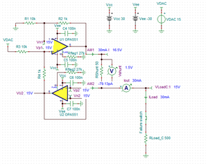
As depicted in my previous post here I use a Howland Current Pump for delivering precise current to a load for a testing facility. I've changed the original OPAMP with OPA551 that delivers more output and has higher output voltage range (+-30V)
Due to the circuitry it won't never deliver more than 30mA to the load, way below the datasheet rated maximum 200mA specs however I will know for sure that it will work with saturated outputs a lot of time.
I explain. The testing facility is designed to stress-test the sensors (the load attached to the output) for months (even years). During this period the load that has an initial impedance of a couple of ohms (400-500) will increase its value until it literally breaks apart (above 1k of resistance the test is considered failed but the test still goes on - reaching Mohms).
Now simulation shows that above 1k of the LOAD the input of both OPAMPs reach their input voltage range limit and OPA551 saturates. Apart from reducing current output is it harmful for the OPAMP to work in such a condition for maybe months? What will happen in internal circuitry? Will such a condition trigger a Thermal flag?
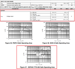
Looking at the datasheet I see no remarks on the Absolute maximum differential voltage rating table applied to the inputs.
I was thinking since in Howland Current Pump the input of both OP-AMPS are held at same voltage in "normal-linear" operation can a circuit be implemented whenever there is an unbalance of the differential voltage to be monitored from an MCU indicating there is saturation?
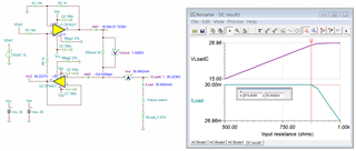
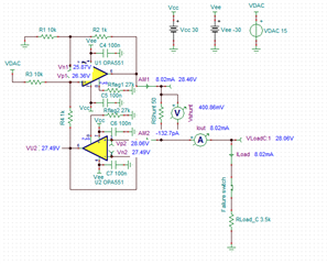
I am posting the TINA-TI simulation and a picture of linear, saturated and open-circuit (not such a big difference from previous saturated mode) output voltages and current.
Linear Mode:
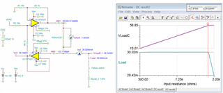
Saturated Mode:
Open Circuit - Broken sensor Mode:

Tina-TI simulation:
Best regards and thanks to all.
Stefano