This thread has been locked.

If you have a related question, please click the "Ask a related question" button in the top right corner. The newly created question will be automatically linked to this question.

INA826: INA826

Part Number: INA826
Other Parts Discussed in Thread: INA823

hello with the Demo board connect to a pressure sensor the INA  output has a variation of +-7mv.

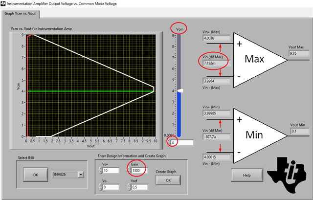
The 4" inch wire connects the PCBA to the sensor. based on what I measured, the  826 may not be appropriate for such a high gain.

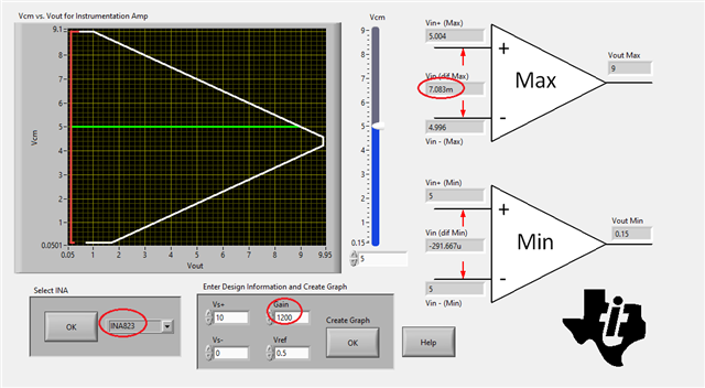
Would an 823 would be a better choice, 

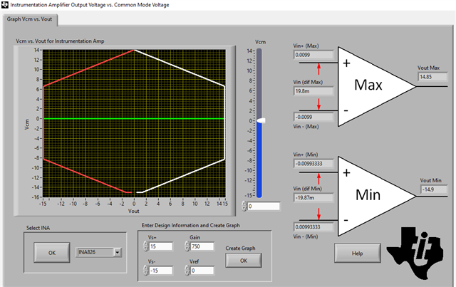
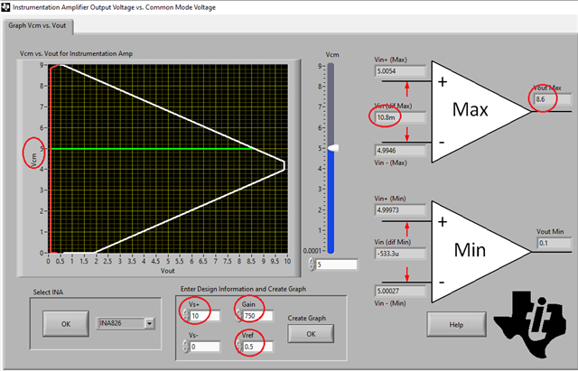
Spec: input is 5V CM  with a gain 1.4v, excitation voltage 10V with an offset off .5V    Gain ~750 output swing ~0- 5V

The 826 was chosen because of its rail-to-rail capabilities. 

  • Allen,

    First, what is the supply voltage you plan on using?  Also please clarify apparent conflict between " +/-7mV input" AND "input is 5V CM  with a gain 1.4v, excitation voltage 10V with an offset off .5V    Gain ~750 output swing ~0- 5V." This is very difficult to understand.  I would suggest you draw the circuit (even by hand) and attached its image using INSERT button below. Please make sure to show all the conditions including Vsupply, Vcm, Vref, gain,etc.

    Keep in mind that the linear input voltage range of most instrumentation amplifiers is a function of the supply voltage, input common-mode voltage, reference voltage and gain.  Therefore, the rail-to-rail output (RRO) may not be possible even when using RRO INA if you do not properly set the conditions of the application. Please download TI Engineering Analog Calculator using link below and use the Instrumentation Amplifier Output Voltage vs Common-mode Voltage function to determine linear input/output voltage range - see below.

    https://www.ti.com/tool/ANALOG-ENGINEER-CALC?keyMatch=INA%20CALCULATOR

  • I'm unable to insert a pic, Is an email address available.

    To move forward

    supply: 10V

    INA 826 Ref : 500mV

    Vcm :5V 

    the sensor and supply share the same ground 

    With the pressure sensor connected to the INA, with no applied pressure. the output of the INA is 500mV +-7mV

    thanks 

  • Under conditions outlined above, INA826 would be able to accommodate the input voltage from 0 to 10.8mV (Vout=0.5V+750*10.8mV=8.6V) - see below.

    If you lower the Vcm down to 4V, you could increase the gain up to 1300 and still accommodate the input signal range from 0 to 7.2mV - see below.

  • Hello Marek, comparing the noise of the 826 and 823, ( 21nV @  Gain 1000 vs 20 @ Gain 100), the 823 has lower noise.

    For some reason, the engineering cal does not run on my computer. Can you rerun the output curves using the 823 also I don't believe the 823 is rail to rail, can you confirm if this is the case.

    thanks 

  • Allen,

    The difference of 20nV/rt-Hz vs 21V/rt-Hz is insignificant taking into account that the normal noise process variation may be as high as 20%.

    As far as the output swing goes, the only difference between INA823 and INA826 is 150mV to negative rail vs 100mV, respectively, while they both can get within 150mV of positive rail.  Thus, with Vcm of 4.4V INA823 does exactly the same as INA826 - see below.

    However, with Vcm of 5V the output swing of INA823 is higher 9V vs 8.6V)  allowing gain up to 1,200 for 7mV input - see below.

  • hello Marek, I thought the noise would scale with gain, why use different a different gain value to measure noise.

    based on the data sheet, which is the better device?

    What happens when the input results in a output at or below 150mV, 

    thanks

  • Hi Allen12, 

    INA826 and INA823 are very comparable, see the comparison below. 

    Please let us know the design requirements, and we can simulate circuits for comparison purposes.  

    What happens when the input results in a output at or below 150mV, 

    You may consider to use negative supply rail, if the input differential input is below -291uV. In order to simulate the circuit, we need to know the input operating range of pressure sensing impedance, say the pressure transducer is operating at 997Ω -1kΩ range, IA's output range, gains and Vref etc.. 

    Best,

    Raymond

  • The output noise scales with gain BUT 20nV/rt-Hz and 21nV/rt-Hz noise spectral density refer to the input and NOT the output noise - see below. Vout_noise_rms=Vnoise*sq-rt(BWn)*Gain where Vnoise is the input noise spectral density and BWn is the noise bandwidth.  In terms of the noise INA823 and INA826 are virtually identical. Allowing the output to get closer than 150mV from the rail pushes the output transistor into saturation resulting in a signal distortion.