This thread has been locked.

If you have a related question, please click the "Ask a related question" button in the top right corner. The newly created question will be automatically linked to this question.

TLV7031: Zero crossing detection is not at 50% duty cycle

Part Number: TLV7031
Other Parts Discussed in Thread: TLV3491, TLV3201, TLV7011, LM393-N, TLV9031, TLV9032

Hi,

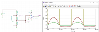
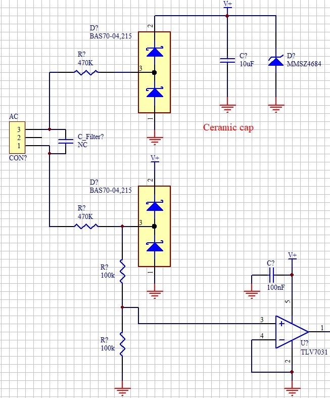
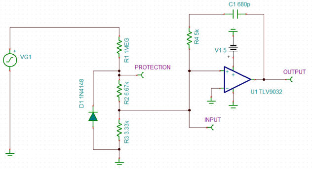
i built a 60 Hz zero crossing prototype circuit for 220 VAC mains power, but the output of TLV7031 comparator are not at 50% duty cycle.

I tested with TLV3491(i have this in my inventory) too and same problem.

I wanted to test with TLV7011 or maybe TLV3201, but TLV7011 i dont encounter($5 in some place) and texas instruments dont provide samples to Brazil anymore.

Input Positive cycle = 8,33 ms 

Input Negative cycle = 8,33 ms

Output Positive cycle = 8,42 ms

Output Negative cycle = 8,26 ms

What may be the problem ?

offset ?

Internal hysteresis ? But TLV3491 does not have hysteresis, only TLV7031 !!!

 propagation delay of only 3 µs ?

Is there a (simple) solution to get 50% duty cycle ??

Thank's.

Video:

Blue = positive comparator input(vi+), vi- is at ground

Yellow = comparator output 

https://youtu.be/yOmY0KqYAZA

  • Rangel

    Thanks for your post.  There must be something fundamental preventing you from obtaining the results you anticipate.  Please provide the circuit you are using and I will review.

    Chuck

  • Hi Rangel,

    your circuit has the disadvantage that the input signal exceeds the common mode input voltage range of TLV7031. This drives the TLV7031 into saturation and very probably causes the timing error.

    The datasheet of LM393-N shows a very nice circuit which you can easily modify to your needs:

    https://e2e.ti.com/support/amplifiers-group/amplifiers/f/amplifiers-forum/994297/lm324-gives-constant-output-even-if-no-input-is-present/3673340#3673340

    Kai

  • snoa999.pdf

    In the Texas Instruments app notes in annex, the input signal exceeds the common mode input voltage too, at least in the negative part. I tested with both tlv7031 and tlv3491 and both had the same problem.

    VCM of tlv7011 and tlv7031 are the same VEE to VCC + 0.1.

    VCM of tlv3491 is (V–)– 0.2 V to (V+) + 0.2 V. 

  • Rangel

    I believe Kai has offered an interesting option to consider.  I would also like to suggest a circuit like this.  The resistor divider that is across the diode could even be modified to reduce the negative voltage swing but I would not anticipate an issue with this implementation because it is current limited.

    Chuck

    240V zero cross detect tlv7031.TSC

  • Chuck,

    The diode i am using in the circuit has a forward voltage of just 0.3 volts.

  • Thanks Rangel

    Then the main difference between what I am suggesting and your circuit is preventing the input from going beyond the supply.  My simulation would not model any saturation that may occur and cause the delay (non 50% duty cycle).  I am curious the impact of switching to the TLV7011 which is 10x faster.  I would consider trying both of these options if possible.  If you can obtain samples, TLV7011 is pin compatible.

    Chuck

  • I can't get samples.

    I think Hamilton K. Ignacio no longer works at Texas Instruments here in Brazil.

    Could you send me 5 samples of the TLV7011 ?

    Thank's Chuck.

  • Rangel

    Since that is the case, I suggest you try dividing down the input so the signal remains within the supply limits first.

    In the meantime, I will reach out offline with a friend request and loop in our marketing team to see how best to support.

    Chuck

  • Hi Chuck, 

    i think that your friend request has expired.

    Could you sent again ?

    Thank's.

  • Hi Chuck,

    i tested it with a voltage divider using two 470K resistors and it changed almost nothing.

    i tested it with a voltage divider using two 100K resistors and it changed almost nothing too.

    I'm thinking that the problem is not the saturation of the comparator input.

  • Rangel

    Sorry this isn't working yet but we will figure it out.  I have some parts in the office that I can try out.  Just so I know exactly what you built, did you try the 3 resistor network with the diode that I suggested?  If not, just send me a snapshot of what you built after the initial attempt.  I hope to get on this tomorrow but latest will be Wednesday.  I will report back with my findings.  Thanks for your patience.

    Chuck

  • Hi Chuck,

    below follows the circuit:

  • Thanks.  I will find some samples to experiment with and report back.

    Chuck

  • Rangel

    Just wanted to update you on my findings.  I built the circuit and also noted the timing of the positive and negative pulses being off by 10's of usec.  However, when I switched devices, I noticed something interesting.  With one device the positive pulse width was greater than the negative and on another device it was the opposite, the negative pulse was wider than the positive.  Since the slope of the sine wave input is not very fast when passing through the switching threshold, input offset voltage could be causing the timing differences we are seeing.  I simulated adding offset and have seen this as well.  I also tested on the bench with a square wave input instead of a sine wave.  When I did this, the input duty cycle and the comparator output duty cycle matched.  So I think offset could be cause for the skew values we are measuring.  When you try different devices, do you get the same skew or does it change?

    Chuck

  • Hi Chuck,

    I only tested with one tlv7031 and with one tlv3491, and de skew of both was similar.

    When i tested with the voltage divider using two 470k and after with two 100k i noted some significant change if i remember(both tests with tlv3491 only).

  • I still think its the offset that is causing the error.  I ran simulations with +10mV and then -10mV of offset to test the theory and my positive pulse width changed by approximately 150us.  I am sure the parts we are testing with are not that bad but I exagerated the offset to see the difference.  Also, when I tested with a square wave, input and output duty cycle matched.  With the faster rise and fall times, offset becomes fairly irrelevant.  So seems to support the theory.  We have a dual channel device, TLV9032 with fairly low offset and still relatively low supply current.  Our single channel version is in development and will have same low offset spec.  This will be the TLV9031 but won't be available for a few more months.  I am not sure that I have much more to offer you for assistance but I hope this information helps.

    Chuck

  • Hi Chuck,

    could you assemble the real circuit with the tlv9032 and test ?

    Thank's.

  • Rangel

    I should have some devices that I can test but it may not occur until early next week.  I can report back then.  What sort of accuracy are you seeking?  Would be nice to learn more about your application.  If needed, you can share offline.

    Thanks,

    Chuck

  • Hi Chuck,

    Ok to me to early next week.

    I would like the delay between the zero crossing of the electrical network and the generated signal to not exceed 20us. I would also like this delay to be symmetrical (equal or very close) at both zero crossings.

    I may even be exaggerating for my application, however, I would like to have a well designed circuit now.

    The zero croosing need to be isolated too, so, the 20us delay, includes the isolation circuit delay as well.

    The cost is also important.

    Low power too, i am using the eletrical network to power the circuit, so, the input resistors dissipate a lot of energy if it's not low power.

    Thank's.

  • Thanks Rangel for sharing the extra details.

    We will report back with our findings.

    Chuck

  • Hi Rangel,

    Thank you for your patience. I just wanted to update you with our findings. TLV9032 has low offset voltage and we were able to see that the duty cycles of the output and input were matched and the accuracy was improved. However, this device does not internal hysteresis, meaning we saw chatter on the edges of the output. To resolve this, we did AC hysteresis by having a capacitor in the positive feedback loop of the comparator in series with a resistor. The capacitor passes the fast edge of the output which creates a brief kick to the input signal and moves it away from the threshold to stop any chatter. The resistor just attenuates this kick amplitude. Normally this method is used when you only need hysteresis for a short amount of time. With our circuit, I found the chatter was most reduced in the several hundreds of pF's for the cap and in the several Kohm's for the resistor. You'll need to play around with these values to see what gives you the best results. You may also need a bypass capacitor to stabilize your supply and reduce any noise. 

    -Chi

  • Hi Chi Nguyen1,

    Can you post the circuit ?

    Interesting finds in your tests.

    The strange thing is that i was unlucky (or lucky) to get an integrated circuit (TLV7031), with high offset, because the datasheet specifies that the TLV7031 has a typical offset of +/- 0.1 mV, but it can reach +/- 8 mV .

    Thank's.

  • Hi Rangel,

    See attached for the circuit using the TLV9032 with AC hysteresis. Keep in mind that although offset is a factor, others such as your input signal frequency and edge, speed of the device, and measurement error and precision from your scope could also be affecting your results. 

    240V zero cross detect tlv9032.TSC  

  • Hi Chi Nguyen1,

    I'm still having doubts about your last statements.

    Did you get to assemble the circuit in practice ?

    Same circuit ( all connections and values ) ?

    Connected to the electrical network 220V 60Hz ?

    Thank's.

  • Hi Rangel,

    We did not use a 220V source as that would be a huge safety hazard for us in the lab, but yes we did assemble the circuit instead with a 10V 60 Hz source and R1 as 50k (which would be similar to a 220V and 1Meg). 

    -Chi

  • I understand.

    You don't have an isolating transformer in the lab 1:1, 220V to 220V ?

    The 470K resistors also need to be one in phase and one in neutral (can influence the circuit).

    If it were possible to assemble the circuit exactly as I did and with the same components, I believe the results would be much more reliable.

    Thanks.

  • Rangel

    This is a very interesting application and we very much appreciate your use of the forum.  However, we cannot take our support beyond this point.  We have done our best to make suggestions based on our knowledge of the comparators and what we have seen in our experiments.  If you have any further questions regarding our comparators, please feel free to post your questions and I hope you can find a solution that best serves your application.  

    Chuck

  • Hi Rangel,

    these circuits -however brilliant they may be- suffer from the important fact that the real mains voltage can hugely differ from a pure, clean and ideal 60Hz sine wave. This is often overlooked and can make lots of trouble when trying to find the "exact" moment of zero crossing.

    The simpliest remedy is to add some simple RC low pass filtering in front of the zero crossing detector to suppress at least some of the harmonics, transients, glitches and dips.

    It's also recommended to use a mains voltage filter in your application, not only to suppress the noise from outside but to also suppress the swtiching noise generated by your application itself.

    There's a lot development work to do to make all this fit properly together which goes way beyond what can be helped in such a forum.

    Kai

  • Hi Kai klaas69,

    I know all about this, but, at least for now this is not the problem.

    The comparator input signal has 50% duty cycle(or very close to it), the comparator output does not have 50% duty cycle.

    Maybe the "high impedance of comparator input signal(470k)" are causing the problem or diode bridge or something else in comparator(offset or internal hysteresis or both).

    The frequency is only 60 Hz, imagine having accuracy with a high frequency signal like 15kHz audio or worse in the MHz range.

    Thanks. 

  • Thanks Kai for your continued excellent support.

    Rangel

    Since I do not believe we can provide any additional support on your application, I will be closing this post.  I hope you can make use of some of our suggestions.

    Chuck