This thread has been locked.

If you have a related question, please click the "Ask a related question" button in the top right corner. The newly created question will be automatically linked to this question.

LM358A: application questions

Part Number: LM358A
Other Parts Discussed in Thread: LM358, TLV9002, LM2904

Hello,

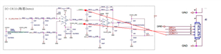
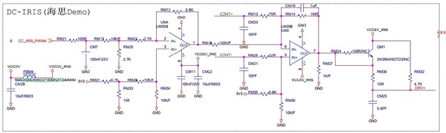
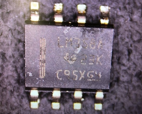
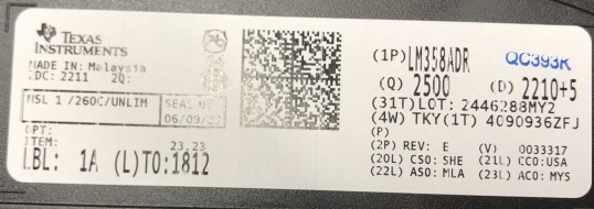
One customer bought LM358A from TI website for his camera application, but he found that the output voltage is lower than actual output, it is about 2.36~2.42V, but it should output 2.8V.  He bought 2500pcs 10-300-0325-01 LM358ADR, and spot check 125pcs, the failed rate is 100%, and the silkscreen is 23K.

Best regards

Kailyn 

  • What are you referring to with "output"? Pin 1, pin 7, or the node labelled "DRV+"?

    A common mistake is using the LM358 outside its valid common-mode voltage range (VCM); with a 5 V supply, it is not guaranteed to support voltages larger than 3 V. If this is the problem, a rail-to-rail opamp like the TLV9002 will help.

  • Hi Kailyn,

    why do you short Ube of QM1? When not being disburdened by QM1, U9B must drive a much higher output current and the output voltage of OPAmp will collapse. And RM27 additionally heavily increases the load current.

    Kai

  • Hello Kailyn,

    How much output current flows at 2.8V?

    Can you measure voltages at some other points?

  • 要怎么测试:用老的芯片测试,还是用新的芯片?
    用老的LM358A的DRV+可以达到3V,用新的LM358A只有2.3V左右,用其他运放(比如:LM2904等)也能达到3V。

  •  我们测试的输出是 DRV+

  • .QM1 and RM24 soldering, QM1 can be turned on. Removing RM27 on the same set of boards is still the same result

  • The old LM358A, DRV + voltage 3.0V, output current 15mA

    All of the above are tested on the same set of boards

  • If QM1 and RM24 are soldered, can QM1 be turned on? Removing RM27 on the same set of boards is still the same result.

  • Does the CONT- and CONT+ nodes leave this schematic page? 

  • Qun,

    The feedback resistor is high , 1M and inverting input resistor is very low, 75 ohms.  This is a signal (AC) gain of -13,333 and addition there is a DC offset that will be amplified by a gain that could be as low as 11 if CONT+ has no DC conduction path. If there is a path then the offset gain would be higher.

    If CONT- provides no DC current then pin 5 would be 1.9643V but supply voltage and resistor tolerances could affect that. You want 2.8V at output ; once again I'll assume no CONT+ DC current ; so pin 1 would need to be (2.8 - 1.9643) / -10 + 1.9643 = 1.8807 

    To go any further, I need to know voltages at other points. The more the better. 

  • RM21:3.3V
    RM20:0.87V
    RM33:2.16V
    CONT+:1.98V
    CONT-:1.98V
    DRV+:3.0V
    Pin1:1.63V
    Pin2:1.09V
    Pin3:1.08V
    Pin4:0V
    Pin5:1.98V
    Pin6:1.98V
    Pin7:3.1V
    Pin8:4.93V

  • Qun,

    I simulated the schematic using perfect op amps and added values on the left side.

    3.300V RM21:3.3V
    0.859V RM20:0.87V
    2.13 V RM33:2.16V
    1.96 V CONT+:1.98V
    1.96 V CONT-:1.98V
    1.59 V Pin1:1.63V
    1.07 V Pin2:1.09V
    1.07 V Pin3:1.08V
    0V     Pin4:0V
    1.96 V Pin5:1.98V
    1.96 V Pin6:1.98V
    5.75 V Pin7:3.1V
    n/a Pin8:4.93V

    The voltage across CONT is extremely important 

    246uV was needed to get output to 3.1V

    Is this a new application? If not, was it based on a successful design?

  • utput of the old LM358A can reach 3V, and the new LM358A can only reach about 2.3V. What is the reason?
    what's the differece between two of them?

  • utput of the old LM358A can reach 3V, and the new LM358A can only reach about 2.3V. What is the reason?
    what's the differece between two of them?

  • Qun,

    There can be two reasons:

    1) The op amp doesn't think it needs to provide over 2.3V (it nulls it inputs when output is 2.3V)

    2) The op amp is incapable of providing more than 2.3V (it has a significant positive input difference voltage but the output current limit is stopping further voltage increase)

    #2 is the easiest to test, just short pin 6 to ground. How high does pin 7 become?

  • utput of the old LM358A can reach 3.1V, and the new LM358A can only reach about 2.39V. 

  • Hey Qun, 

    Are your results provided above, the ones to Ron's question? 

    #2 is the easiest to test, just short pin 6 to ground. How high does pin 7 become?

    It looks like you simply repeated what you had said a few days ago... could you please short pin 6 and let us know what pin 7 is? 

    All the best,
    Carolina

  • On the same board, why the OLD LM358A output 3v.
    I undersanding is the same borad output should be same. no matter the new or old.
    is the Design or Production process changed? or other reason cause the different output?

  • short pin 6 to ground.
    pin 7 :
    old LM358A :3.1V,
    new LM358A:2.39V。

  • Qun, thank you for making that clear.

    LM358A has a voltage spec for 5V operation. It is 3.5V or better with a 2k load  which is 3.5V/2k = 1.75mA

    Your application has vastly more output current. 

    PCN 20210212001 dated February 15 2021 includes a die revision. The new die has better output voltage versus current load and a more defined current limit. If 'new' is the problem then the output load is engaging the current limit. In other words, the op amp is protecting itself. 

    I could suggest an alternate op amp that has greater output current. How much current do you need?