This thread has been locked.

If you have a related question, please click the "Ask a related question" button in the top right corner. The newly created question will be automatically linked to this question.

OPA170 Abnormal Behaviour

Part Number: OPA170
Other Parts Discussed in Thread: TINA-TI, TLV9101, OPA990, , LM2903-Q1

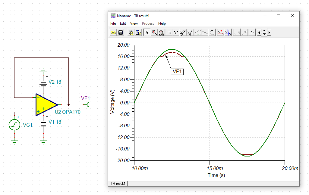
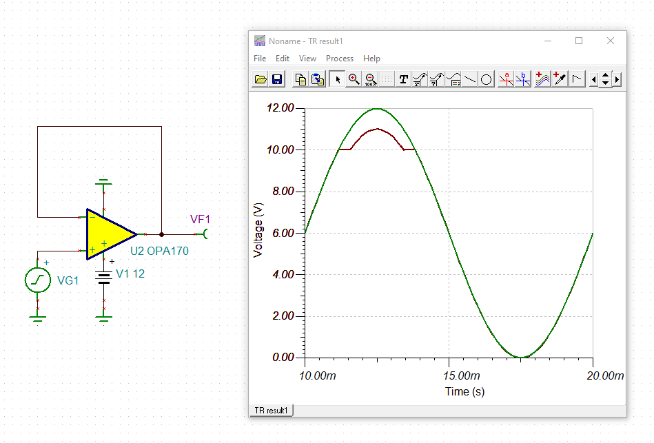
Hello, i am designing a circuit consisting of OPA170 and hope anyone could answer what's wrong with the opamp (as per item#2). all the supply information as per schematic below. V+ and V- are still lower than the supply.

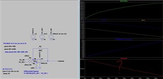
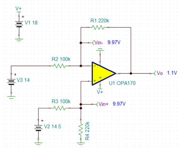
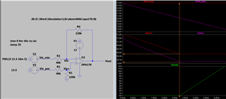
1. in the below circuit i am using Rf=220k and Rin=100k. the 3rd plot shows the feedback calculation (Rf/Rin)(V3+ - V3-) and the 4th plot is the actual simulation. 3rd plot and 4th plot are identical.

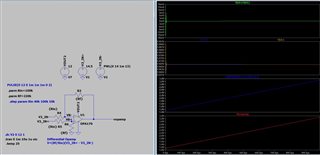
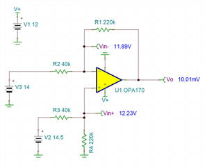
2. in the below circuit i am using Rf=220k and Rin=40k. the 3rd plot shows the feedback calculation (Rf/Rin)(V3+ - V3-) and the 4th plot is the actual simulation. however, the simulation is not as per the calculation

  • Hi Fairuz,

    The simulation program you are using doesn't look like TINA-TI or Pspice for TI. We only test our device models in those two TI approved simulation programs and cannot guarantee they will work properly in any other program. First thing I would do is to switch to a TI approved program. 

    Your circuit gain is what's causing issues. Let's look at the circuit when Rf = 200k and Rin = 40k. See below. 

    Notice the input voltages at both pins don't match, thus making the op-amp act like a comparator in this case, but also they are violating the common mode input voltage range of the OPA170 as shown below: 

    The common mode voltage should be at least two volts below the positive rail. This problem didn't occur when you had Rin = 100k as it's not violating the common mode range. 

    It's always easy to forget the input pins limitations. Happens to us all! If you'd like a more in-depth explanation of the input limitations, please check out the TI Precision Lab video: Input and output limitations - Common mode voltage

    Let us know if there's anything else you need! 

    Best Regards,

    Robert Clifton 

  • Hi Robert, thanks for the input. I did change the V2=13.5V and V3=13V and the Vin+ Vin- within the voltage supply (edited : for 40k Rin). but the output still behaving the same which the Vout ~ 10mV instead of ~1V.

    I did check the OPA170 datasheet and it is stated "Note that these devices can operate with full rail-to-rail input 100 mV beyond the positive rail, but with reduced performance within 2 V of the positive rail". I thought Vin should OK since below supply  but i not sure what is mentioning reduced performance as the gain is not high.

    i will watch the link after this.

  • Hi Fairuz,

    I did change the V2=13.5V and V3=13V and the Vin+ Vin- within the voltage supply. but the output still behaving the same which the Vout ~ 10mV instead of ~1V.

    Which circuit do you mean? With 40k or 100k?

    Kai

  • Hello Kai, 40k. i thought i can use rail-to-rail and not (V+) - 2

  • Hi Fairuz,

    section 7.7 specifies the common mode input voltage range and clearly says: Stay below (V+)-2V.

    It's true that the footnote says that the input voltage range can be extended to V+ but it should be clear that the OPAmp doesn't work properly then, otherwise section 7.7 would allow the input voltage to be V+.

    Compare the specs in table 2 with the specs in section 7.7. Look alone at the huge difference of the open-loop gain. From this it should be clear that the input voltage range between (V+)-2V and V+ should not be used in a precision circuit. Yes, the OPAmp will work somehow but not very good.

    Figure 37 says that no phase reversal occurs. That's what is meant by "the input voltage range can be extended to V+", that no phase reversal will occur:

    fairuz_opa170.TSC

    Kai

  • Hello Kai, thanks for the reply. i guess that is my real question, how to use table 2 as my input will consist 10-12V with 12V supply. Does the actual opamp behave similar to simulation? i believe the gain is not high with Rf=220k, Rin=40k. does the differential formula does not work on 10-12V (V - 2 to V + 0.1) or how should i handle this?. Should not use rail-to-rail input at all? below simulation shows Vin between V-2 to V not works properly and below V-2 is working.

    The reason i am asking is due to my circuit board will be using using input & voltage as stated. V- will track any voltage drop and pass to Vout using differential formulae to next stage.

    thanks!

    Fairuz

  • Hi Fairuz,

    I would not use the input voltage range between (V+)-2V and V+ at all. You can easily accomplish this by modifying the input voltage divider.

    Kai

  • Hi Fairuz,

    To add to Kai's comments, you could take a look at using the OPA990 or TLV9101 rather than the OPA170. These devices have a wider Vcm range, though I would still recommend adjusting the input voltage divider. 

    Best Regards,

    Robert Clifton 

  • Hi Robert, thanks for the recommendation. this looks great but it only works on 125C. my requirement as below.

    150C, Vsupply = 12V, Vin =12V. and i will use as both differential and comparator (differential out will feed into comparator)

    currently i am using OPA170-EP however as issue stated above, Vin seems only working at (V+) -2V.

    If you have part suggestion do let me know. i did check on LM2903-Q1 but when i try the PSPICE simulation model the output seems 0V, may try again later.

    fairuz

  • Hi Fairuz,

    all these problems can be solved by using suited voltage dividers which guarantee that the input voltage doesn't exceed the specified common mode input voltage range.

    Kai

  • Hi Kai, thanks, i will recalculate since i cannot use rail-to-rail input. will post again if i encounter issue. but if there is as per my request spec (150C 12V supply and input), do let me know so i can consider in next design.

  • Hi Fairuz,

    I don't believe there should be any other concerns for your design.

    If you do encounter any other issues, please post a new E2E thread. That way if anyone else has this issue it will be easier for them to search it. 

    Best Regards,

    Robert Clifton

  • Hi Robert and Kai, thanks for the support. i will make new thread.