This thread has been locked.

If you have a related question, please click the "Ask a related question" button in the top right corner. The newly created question will be automatically linked to this question.

AMC1200: Additional Shunts

Part Number: AMC1200

Hi Team,

A customer is using AMC1200 and would like to connect it using different shunts as shown in the image below. The shunts were for current measurement

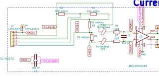
The shunt values are 30mOhm; 30 mOhm; 240mOhm; and 900 mOhm, to get currents of values 10Ampere, 5Ampere, 1 Ampere, and 250 mA. with 300 mV at full scale of each range. For example, 10Ampere through the 30 mOhm will give 300 mV so does the 5Ampere through the 30mOhm+30mOhm, etc.

Would it be okay to do this or will they encounter errors?

Regards,

Marvin

  • Hi Marvin,

    This is an unconventional approach and not one that I would recommend. In the current configuration, the solder joints of the shunt resistors in series will add additional resistance to the sensing nodes. Difficult to say what other type of errors they may see such as parallel currents, without additional detail on the connector and how they plan to switch current in and out of the front end. 

    I would also recommend re-naming the "GND2- " net at the shunt and connector node. As the schematic is currently named, the ferrite bead will be bypassed and provide no benefit. 

    What is the accuracy target for each measurement and will any calibration be performed?

    Does there need to be isolation between the different current levels? 

    What type of shunt do they plan on using and are the listed current levels nominal or short-time maximums? 

  • Hi Alexander,

    Thank you for your assistance, please see my response below:

    What is the accuracy target for each measurement and will any calibration be performed?

    Regarding the accuracy of the current measurement, 1 to 2% of error is acceptable.

    Does there need to be isolation between the different current levels? 

    No need for channel to channel isolation , single channel only will be used at a time so let's say 5 Ampere range is used in this case the current will move through (30 mOhm + 30 mOhm) X 5Ampere = 300 mV full scale. The connector is going to be a standard green terminal block that accepts up to 15 Ampere.

    What type of shunt do they plan on using and are the listed current levels nominal or short-time maximums? 

    The customer was using Surface Mount Current sense resistors. The listed Values are nominal maximum values for each range.

    Here is a list for the shunt resistors that they are planning to use:
    1)RL1206FR-070R9L (900 mOhm)
    2)RLP73K3AR24FTDF (240 mOhm)
    3) FCSL90R030DER (30 mOhm)

    I hope this helps.

    Regards,

    Marvin

  • Hi Marvin,

    I took a quick look at the shunts using the "Shunt Rating Calculator" in our "Isolated Amplifier Current Sensing Calculator". https://www.ti.com/lit/zip/sbar020

    Please note AMC1200 is not included in the calculator since it has a different input structure that is not applicable to these calculations. The customer may want to consider a higher accuracy device such as AMC1300B. 

    1)RL1206FR-070R9L (900 mOhm) - Looks good, should be able to sense up to nominal current up to 110C ambient temperature safely. 
    2)RLP73K3AR24FTDF (240 mOhm) - OK up to 125C
    3) FCSL90R030DER (30 mOhm) - Using the calculator, I am concerned that this shunt may have difficulty with a nominal amperage of 10A. However this calculator was designed for 2 terminal, manganin shunts and I expect the wide package, metal foil resistors such as this to have better capabilities - especially if adequate heat dissipation is designed. To be safe, I would recommend increasing the current rating - at least of the one sensing 10A.

    Since the resistances of the resistors is so high, this may work without significant error - but it is not a common approach. Please keep me posted on progress and let me know if the customer runs into any issues. 

  • Hi Alexander,

    Here is the customer response:

    Regarding the current rating of the shunt resistor, actually, its power rating is 4W, and the power dissipated by 10Ampere in 30 mOhm resistors is 3W (https://www.ohmite.com/assets/docs/res_fcsl.pdf) so I don't actually understand your recommendation regarding this resistor.

    Also for the GND3- net that you suggested renaming between the ferrite bead and the connector. The same connection is present in the evaluation board of the IC AMC1200, you can find the circuit in page 49 (https://www.ti.com/lit/ug/tidua58/tidua58.pdf#page=49)

    I don't understand how do you believe it's bypassing the ferrite bead while the two nets before and after are completely different.

    Please let me know if you need more information from the customer

    Regards,

    Marvin

  • Hi Marvin,

    I have seen solder joints having a resistance of 100µ...1mOhm. This would be 1/30 or 30mOhm.

    Kai

  • Hi Marvin,

    For continuous operation, it is recommended that shunts are not run at more than two-thirds (2/3) the rated current under normal conditions of use. Excessive heat dissipation in the shunt resistor will also cause resistance drift, resulting in additional measurement error. The rated current of this resistor is 11.5A, which means I would not recommend operating continuously beyond 7.7A, 1.8W. 

    I did not participate in the design that you've referenced. I'll do my best to get in touch with the owner of this design to discuss in parallel, but there are two reasons for adding ferrite beads: attenuating high frequency noise from the nodes to be sensed on the inputs or reducing EMI from the isolated amplifier. For the first, yes the ferrite beads will provide some attenuation benefit; however any mismatch between the two ferrite beads will lead to a differential signal on the inputs. Furthermore, without an additional ferrite bead between the sensing node and the device's high side ground, noise from the sensing node will have a path into the device and potentially the measurement. The CMRR of the device is specified 95 dB up to 50kHz and for most designs all that is needed is a differential anti-aliasing filter. For the second reason, EMI, once again without the third ferrite bead between the devices high side ground and the sensing node, noise from the device will have a path to radiate from the sensing node. 

    I recommend adding a placeholder for the third ferrite bead between the sensing node and the high side ground, then testing performance with and without them to verify their benefit. 

  • hi Alexander, I am the one behind the original question/Schematic.

    1) Can you please tell me if you contacted the owner of the reference design and whats the outcomes of your conversation?

    2) Can you please illustrate by any simple drawing how do you want the third ferrite bead to be connected?

    3) The CMRR  95dB up to 50khz , It's written in the data sheet that the minimum bandwidth is 60kHz What does that even mean ? I can't measure signals below 60kHz?  i am planning to measure as low frequency as DC current.

  • Hi Amr,

    Nice to meet you. 

    I haven't had a chance to discuss this with the designers yet.

    This schematic and layout picture from this document can be used for example: https://www.ti.com/lit/an/sbaa515/sbaa515.pdf

    Minimum bandwidth of 60kHz means that signal above 60kHz may start to see attenuation. Any signal 60kHz or less will not be impacted. 

    Please let me know if you have additional questions. 

  • Nice to meet you too Alex!
    Thank you for your useful reply I have a question regarding the protection of the IC. Let's say the input differential voltage was 2.5V which exceeds the +/-250mV will just clipping occur or will this voltage damage the IC ? Also in the application note above , the designer added diodes with this part number DESD1P0RFW-7 to clamp the signals with overvoltage to either ground or VCC. Could these external diodes affect the operation in any manner ?

    Thank you very much in advance

    BR 

    Amr

  • Hi Amr,

    what sort of overvoltage are we talking about? If it's only ESD, then you can easily add them, although the AMC1200 already contains ESD protection diodes at the inputs.

    But if the overvoltage condition lasts longer than ESD, you will need a current limiting resistor in front of the protection diodes. Then, the leakage current of your ESD protection diodes can cause a voltage drop across the current limiting resistor unwantedly increasing the effective input offset voltage. This would especially be the case, if the current limiting resistor needs to be big because of a big overvoltage and/or if the operating temperature is high (-> increase of the diode's leakage current).

    Another issue is that the supply voltage generation must be able to absorb the input current shunted to the supply rails without exceeding the maximum supply voltage of AMC1200.

    Because of all this, the concrete value of maximum overvoltage must be known first before a concrete answer can be given.

    Kai

  • hi Kai , thank you very much for your answer , I am actually talking about continuous overvoltage not just ESD. The maximum overvoltage is going to be 5V peak to peak 2.5V peak.

    I think the VINN and the VINP can tolerate up to the AMC1200 VCC according to the absolute maximum ratings of the IC. However , I know that the operating range is +/- 250mV , so is it ok if continuous overvoltage of 2.5Vp is applied on the IC inputs as the IC will just clip it or will it affect the IC in any manners ?

  • Hi Amr,

    Protection components will introduce error to the measurement due to tolerance mismatch between them and unaccounted for leakage currents. However, some applications will require these protection components due to expected voltages in the system.

    The conditions that may damage the device are listed in the Absolute Maximum Ratings Table:

    Diodes tied to the high side supply will not turn on unless the applied voltage is higher than the high side supply - which if I understand your description correctly, is not the case for your application. In this case the most effective form of protection will be current limiting resistors to ensure that less than 10mA can flow to the inputs. Further limiting the input current is ideal.   

    For reference, this TIPL video covers how to select a current limiting resistor and appropriate diode: https://training.ti.com/eos-and-esd-adc