This thread has been locked.

If you have a related question, please click the "Ask a related question" button in the top right corner. The newly created question will be automatically linked to this question.

LMH6881 output drift

Part Number: LMH6881
Other Parts Discussed in Thread: ADS4128, OPA657, TINA-TI

Hello,

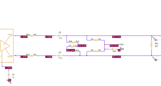
I use the LMH6881 as the second amplifier and the ADS4128 to sample the data. The schematic is below:
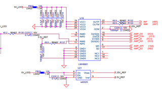
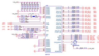
The pulse (pulse width=20ns, pulse period=50ns, tr/tf=2.6ns, Vpp=0.15V) is feed to the LMH6881. We found that the pulse signal drifted downward. (Get from the ADS4128 or test by Oscilloscope is the same) The pulse signal don't drift at the input pin 11 of the LMH6881. 

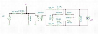
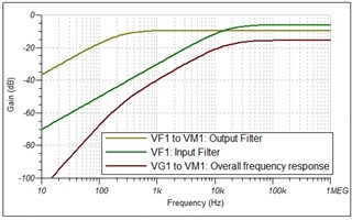
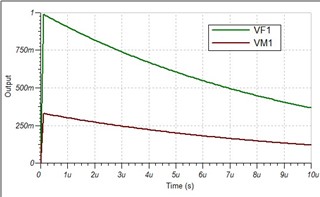
Then we get the simulation project of LMH6881 from TI website. We use the PSpice for TI 2022 to simulate the LMH6881. From the result of the simulation, we find the output of LMH6881 drifted downward too. The schematic and result of the simulation are below:
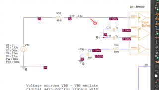
Could you help us analyze the reasons and give us some suggestions for this problem, please? Thanks very much!

Best regards,

MW

  • Hi MW,

    Is this due to the AC coupling? The input signal of 0V to 0.12V has a +0.06V DC average. This is initially injected through the capacitor just like the high frequency signal, but then it slowl bleeds off through some high impedance from the differential outputs to ground. One solution is to give the differential input signal a 0V average. 

    A way to speed up the time constant of the decay is to increase the common mode loading to ground at the output.

    Best regards,

    Sean

  • Hi Sean,

    Thanks for your feedback! Yes, it is the AC coupling.

    1. According to your first suggestion, we need add a convertor to make the single signal to differential signal, then feed into the LMH6881. This way can make the differential input signal a 0V average. Because the amplitude of the input signal is variable (maybe 0~0.3V, 0~0.09V, etc.). Am I right?

    2. And we are very interested in the second option that increase the common mode loading to ground at the output. Could you give us a specific implementation of the circuit, please?

    Thanks again and best regards,

    MW

  • Hi MW,

    1. Yes, but you will probably still run into the same problem if the input signal's average voltage is constantly changing. The main issue as I see it, is that the differential output average decays to around 0V, but at first, the variable average of the input signal is visible.

    2. The easiest way to speed up the decay is to reduce the capacitance of C5 and C6.

    However, the opposite might be a better solution. Can you remove all of the differential loading (R4, R5, R45, R48?)  That might prevent the output from averaging to 0V for a long enough time for your application to work? Then you would not have to worry about inconsistent results during an initial decay time constant.

    Best regards,

    Sean

  • Hi,

    what exactly is drifiting? The differential output signal or only the individual output signals?

    As already mentioned by Sean this is a typical AC coupling behaviour. To minimize it one would need to know the actual shape of input signal. If the input signal is zero for only short periods you can try to increase the AC coupling capacitances. This is done in video circuits, e.g.. In such circuit even big electrolytic caps of more than 100µF can be seen, paralleled by 100nF X7R to allow a path for the high frequency contents.

    So please explain the nature of your input signal.

    Kai 

  • Hi Sean,

    The output voltage fluctuates more fiercely when the C5 and C6 was reduced.

    Hi Kai,

    The input signal is the output of the photodiode transimpedance amplifier---OPA657. The optical pulse width is about 20ns, pulse period is about 50ns; A pulses group have 1~16 pulses. The interval of the pulses group is about 1us. We use PD and OPA657 to convert this optical pulse signal into an electrical pulse signal. We test the input single of the LMH6881 (PIN11) by oscilloscope; We find the pulse signal don't drift; But we find the differential output signal of the LMH6881 drifted downward.

    Thanks and best regards,

    MW

  • Hi,

    ok, the pulse group lasts 1µs. And how long is the pause between these pulse groups?

    Kai

  • Hi Kai,

    The optical pulses are 1-16 consecutive. Then pause about 1us. Then repeat 1~16 pulses.

    Best regards,

    MW

  • Hi Mingwei,

    By "fiercely," do you mean that the DC offset of the differential output decays more rapidly towards 0V? That is, with a shorter time constant? I thought that (#2) was your requested solution. If your pulse group only lasts 1us, now I realize this is the opposite of what you need.

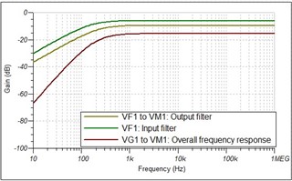
    The amplifier input is 50Ω, not High-Z. This and C12 will create a filter upstream from the amplifier, which we should take it into account also. I am surprised that pin 11 did not drift in your measurement or simulation. It dominates the RC time constant in my simulation.

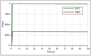
    As always, Kai is correct. A larger capacitor will give you a longer time constant. Reverting all other values to the original circuit, does increasing the input capacitor alone to 10uF sufficiently reduce the drift for your application?

    Please find the analysis below, as well as a TINA-TI simulation file.

    Best regards,

    Sean

    0. Original:

    3. Slower DC decay (drift)

       LMH6881_AC_coupling_DC_deacy.TSC

  • Hi Sean,

    Thanks for your supports! You are right. The input signal drift in the simulation. But I don't see the input signal drift measured by oscilloscope. Here I attached the real signal sampled by ADS4128 (the same as measured by oscilloscope). The Y axis is the signal amplitude; The X axis is the time(the interval of 5ns).

    The sampling clock is 200MHz. The time interval between two points in the figure is 5ns. You will see the baseline (no pulse signal, only noise) level drift down. After about 1us, the baseline level restore normal. We want to keep the baseline level stable. We try many ways(including change C1 to 10uF/22uF or parallel kinds of capacitors, etc.), but failed. Could you give us some advise for this case? Thanks!

    Best regards,

    MW

  • Hi Mingwei,

    you should increase the C5 and C6 as well.

    Is the voltage at VCM stable?

    Kai

  • Hi Kai,

    Thanks for your options! I try increase the C5 and C6 or parallel kinds of capacitors, the output will drift less than before. But the output is still drifting. The voltage at VCM (output from ADS4128) is stable.

    Best regards,

    MW

  • Hi Mingwei,

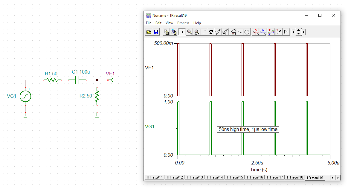
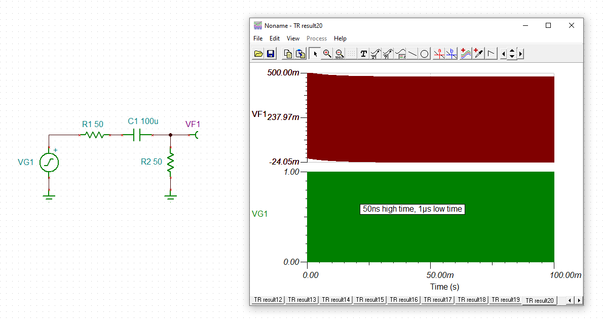
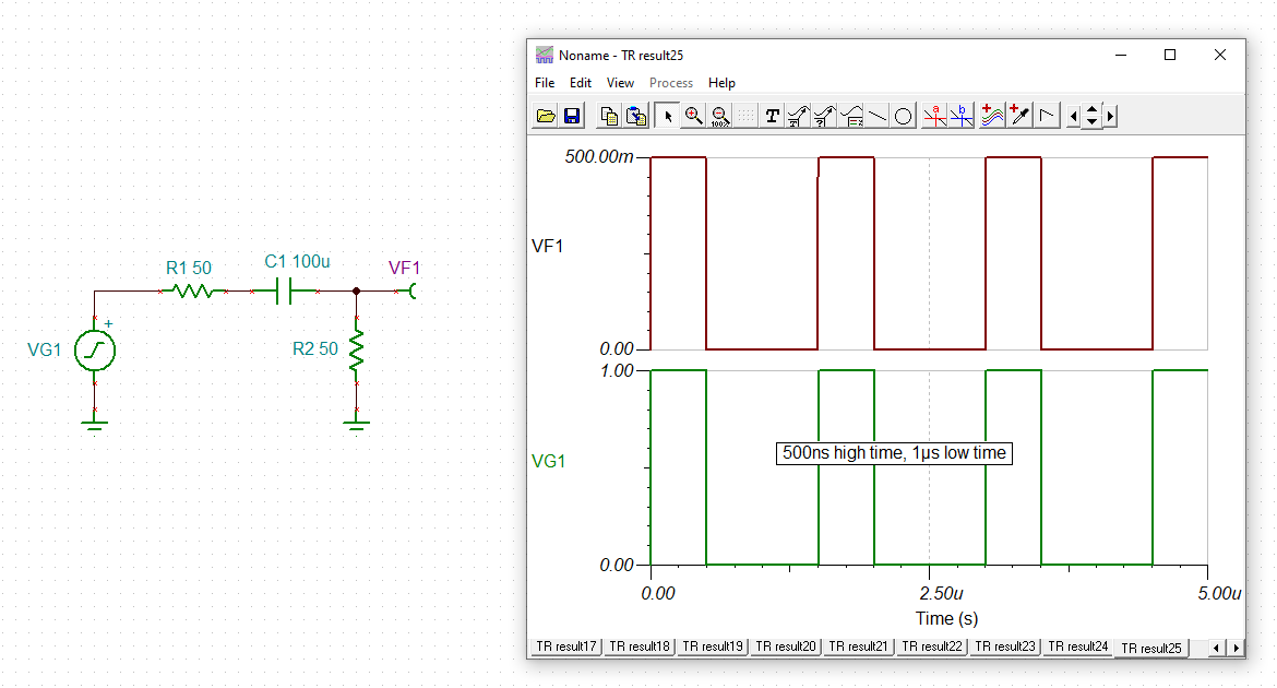
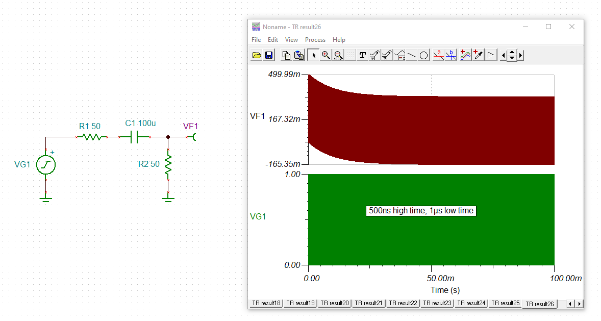
    I think here is a misconception about what AC coupling can perform. In the following I show the behaviour of AC coupling for two different pulse trains, one with 50ns high time and 1µs low time and another with 500ns high time and 1µs low time. These pulse trains shall be very simplified versions of your pulse trains with one and ten 50ns pulses followed by a 1µs low time, which is ok because we are only interested in the averaging behaviour of AC coupling. The AC coupling capacitance shall be very big, much bigger than 100nF:

    mingwei_lmh6881.TSC

    You can clearly see that because of the different number of pulses of the two pulse trains the base lines can never be identical. So, even when the AC coupling has fully settled after a very long time, the base line will drift when changing the number of pulses.

    The same happens when the amplitudes of pulses change, even if the number of pulses of the pulse train is kept constant.

    So, with your special signal there's no way to avoid the base line drifting, even with a huge AC coupling capacitance.

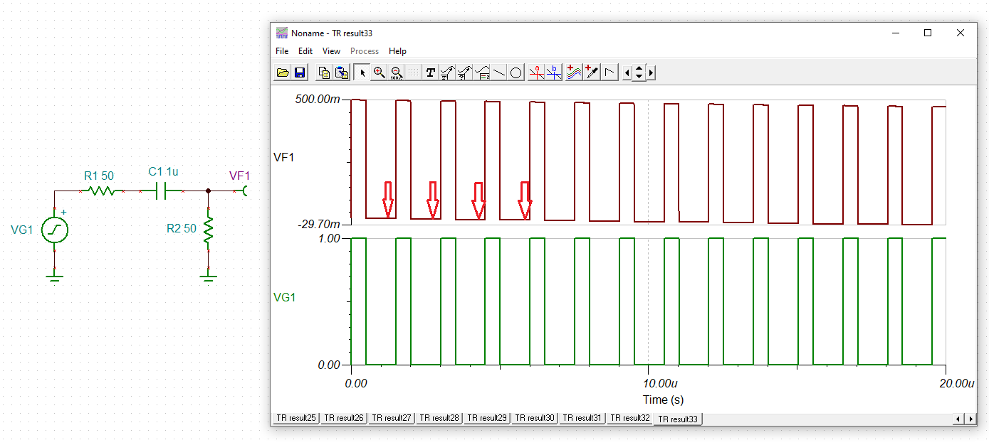
    One remedy is to use a true DC signal handling. Another remedy is to use an adaptive method and to measure the base line in the low time, immediately before the first pulse, resulting in many "momentary base lines":

    The AC coupling capacitance is properly chosen when the base line doesn't drift all too much during a single pulse train.

    The amplitude of pulses is then determined by subtracting the "momentary base line" from the pulse heights. For each new pulse train you take the updated "momentary base line" for the correcting.

    Kai

  • Hi Kai,

    Thanks for your help.

    Best regards,

    MW