This thread has been locked.

If you have a related question, please click the "Ask a related question" button in the top right corner. The newly created question will be automatically linked to this question.

TL074H: Sim Result

Part Number: TL074H
Other Parts Discussed in Thread: TINA-TI

Customer is building a circuit with TL074H OPA. In Tina sim result, there is no problem with phase margin, but it looks the output response is dropping out and abnormal.

Please help to check what happens with the circuit? thanks.

application: Control module for AC inverter.

AFM 10V _TL074H_Step Load.TSC

TL074H Loop Gain.TSC

  • Hello Brian,

    The loop gain wasn't setup correctly. Here is the correct setup and result 

    TL074H Loop Gain2.TSC

  • The feedback drop means the loop is not closed ; in other words the op amp is trying to catch up with the input step.

    The op amp output and final output are far more interesting waveforms. 

  • Thanks. There are two SIM results below, with identical phase margin value, why the output result is difference?

    When Load = 200nF,Phase Margin=83degree,there is a Overshoot as below diagram

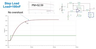
    When Load = 100nF,Phase Margin=83degree,there is no Overshoot.

  • Hi Brian,

    you have made a mistake arround C3. Look how Ron has connected C3 to the OPAmp.

    Kai

  • Thanks for suggestion.

    We've tried to SIM again. 

    From above SIM results with different load, both phase margin are almost the same. but it looks the overshoot is happened when load is 200nF. Why there is no overshoot with 100nF load? thanks. 

  • Hi Brian,

    counter question: Would you really expect that two different circuits (100nF/200nF) show the same step response?

    And it's fully normal that different circuits (even entirely different circuits) showing a different frequency response and different step response can have the same phase margin. There's no contradiction.

    Kai

  • Here the phase stability analysis of your circuit is shown:

    brian_tl074h.TSC

    As you can see the gain and phase curves are different but showing nearly the same phase margin.

    Keep in mind that the phase margin is the behaviour at only one single frequency and different circuits can easily show the same behaviour at this single frequency even if the full curves over all frequencies differ from each other.

    Kai

  • Kai, thanks for details. We are still interested in questions here.

    1. From bode-plot result, how to know overshoot could be happened with load at 200nF?

    2. If circuit output has overshoot problem, how to adjust the feedback RC value or adjusting the bandwidth...etc?  

    Regards

    Brian

  • Hi Brian,

    the experienced designer sees it from the waviness of the phase curve. The 200nF curve shows more ripple than the 100nF curve which can be an indication the 200nF shows a higher overshot than the 100nF.

    But the waviness of phase curve is not a sufficiently good indicator to propely design a circuit, usually. The phase curve of phase stability analysis is merely used to determine the phase margin.

    The correct procedure to prevent overshot is to run the classic step response (and/or frequency response simulation) in parallel with the phase stability analysis. The feedback resistors, the isolation resistor the phase lead capacitance and the load capacitance are altered in small steps until a satisfying performance can be achieved. Usually the application demands the use of a certain load capacitance and a maximum value for the isolation resistor because of too much voltage drop caused by the load current. But the feedback resistors and the phase lead capacitance can usually be altered arbitrarily, at least to some degree.

    Because the OPAmps are highly individual there's no simple rule of thumb telling how to find the proper values of all involved components. And deriving a formula including all the individual properties of OPAmps would be way too complex. Because of that, the best way to find a good design is to run the simulations and find the component values by trial and error. That's exactly why TI has spent so many efforts to generate the Spice models and the TINA-TI reference designs.

    Happily, often there's not only one solution, but many different sets of component values can be used, usually. But the customer has to decide what is important for him, a fast step response without overshot, a maximum flat frequency response, a maximum stable design with much phase margin or a design allowing to accept a wide range of load capacitances. All these requirements can be contradictory and may exclude each other to some degree. So, always a compromise has to be found Relaxed

    Kai