Because of the holidays, TI E2E™ design support forum responses will be delayed from Dec. 25 through Jan. 2. Thank you for your patience.

This thread has been locked.

If you have a related question, please click the "Ask a related question" button in the top right corner. The newly created question will be automatically linked to this question.

INA229: INA229 current sensor reading Manufacture ID

Part Number: INA229
Other Parts Discussed in Thread: SYSCONFIG, TMS320F28377D

I want to use INA229 sensor with the F28377D DSP.

 I am trying to read the manufacturer ID which should be 'TI(0x5449)' as mentioned in the datasheet.

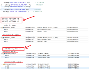
However, the value that I read is 0x0054, 0x4900 or 0x4900, 0x0054.

Found the same question as me. But it seems a little different.
https://e2e.ti.com/support/amplifiers-group/amplifiers/f/amplifiers-forum/1074352/ina229-ina229-current-sensor-reading-wrong-manufacturer-id

Changing the settings of the SPI also has a problem.
CLOCK_PHASE = 1 CLKPOLARITY = 0

The example code is referenced below.
dev.ti.com/.../index.html

Is the spi setting wrong?

Thanks in advance.

  • Hello Andrew,

    Thank you for using the TI forum.

    About the polarity and phase, usually it is that polarity = 0 and phase = 1, however some MCU architectures define polarity and phase differently causing the values to be different. The important thing is that the data lines line up with the clock per the datasheet description:

    You appear to be getting the right values, but maybe it is a format/parsing issue? I recommend looking at the example code from SysConfig: https://dev.ti.com/sysconfig/index.html?product=ascstudio&module=/ti/sensors/currentsensor/INA229. Hopefully this helps you with your firmware issue. If not, message here again and hopefully we can find the issue.

  • I changed the values ​​of polarity and phase.
    Couldn't solve it.
    can you give me some advice?

    Thank you.

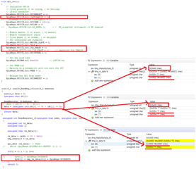
  • for(i = 0; i < 2; i++)
    {
    // byte[i] = SpiaRegs.SPIRXBUF;
    byte[i] = tmp_rx_data16[i] = SpiaRegs.SPIRXBUF;
    }
    return 0;
    }

    I'm not familiar with that MCU but the code above looks suspicous to me. Shouldn't you wait for new data to arrive between those back-to-back reads of SPIRXBUF? There's probably a companion function to spi_xmit() which reads data from SPI.

  • Hey Andrew, 

    I'm adding the TMS320F28377D team to this thread to help with the MCU specific SPI question.

  • Hello,

    A few observations just looking at the code and provided information:

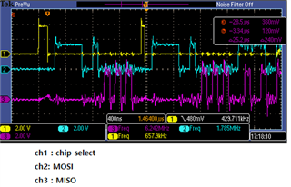
    The SPI is configured for 16-bit characters which will force 16 bits to be transmitted/received on each write to the SPI TX buffer. However, I can't tell from the scope plot if 16 bits are being transmitted in each chip select frame since the SPICLK is not included.

    spi_xmit (tx_data); // Send
    // while (SpiaRegs.SPIFFRX.bit.RXFFST != 1) {}

    for(i = 0; i < 2; i++)
    {
    // byte[i] = SpiaRegs.SPIRXBUF;
    byte[i] = tmp_rx_data16[i] = SpiaRegs.SPIRXBUF;
    }
    return 0;
    }

    This code doesn't look right to me. Since the SPI is configured for 16-bit characters, only a single16-bit read should be done for each SPITXBUF write, not two. The code checking the status of RXFFST should also not have been commented out, otherwise you risk reading SPIRXBUF before there is any valid data in the SPI read FIFO.

  • If you can, please also include the code for spi_xmit(). This function should be writing a single 16-bit character to SPITXBUF.

  • Ah good point, the INA device does send data in 8 bit chunks, so you they may need to configure it for 8-bit reading then read twice.

  • they may need to configure it for 8-bit reading then read twice

    Mitch, correct. For reading manufacturer ID register I would recommend the following:

    • Configure MCU SPI for 8-bit character size
    • Write byte address (SPI simultaneously reads in 1 byte)
    • Wait if RXFFST != 1
    • Read trash byte from SPIRXBUF and discard
    • Write dummy byte (SPI simultaneously reads in 1 byte)
    • Wait if RXFFST != 1
    • Read byte from SPIRXBUF, this is your MSB of your manufacturer ID reg
    • Write dummy byte (SPI simultaneously reads in 1 byte)
    • Wait if RXFFST != 1
    • Read byte from SPIRXBUF, this is your LSB of your manufacturer ID reg
  • Thank you for your kindness.

  • That's correct.
    I read and write with 8BIT, so it works.
    In the meantime, reading and writing in 16BIT did not work.
    Thank you.
  • I was able to read the correct value by reading and writing with 8 bits.
    It seems that it was not possible to read and write in 16-bit.
    Both Manufacturer ID and Device ID read fine.

    The value read. So I shifted 8 bits to the left.

     dt[0] = 0x00
     dt[1] = 0x54
     dt[2] = 0x49

     dt[0] = 0x00
     dt[1] = 0x22
     dt[2] = 0x91

    This is my procedure. 
    • Configure MCU SPI for 8-bit character size
    • Write byte address (SPI simultaneously reads in 1 byte)
    • Wait if RXFFST == 0
    • Read trash byte from SPIRXBUF and discard
    • Write dummy byte (SPI simultaneously reads in 1 byte)
    • Wait if RXFFST == 0
    • Read byte from SPIRXBUF, this is your MSB of your manufacturer ID reg
    • Write dummy byte (SPI simultaneously reads in 1 byte)
    • Wait if RXFFST == 0
    • Read byte from SPIRXBUF, this is your LSB of your manufacturer ID reg
    In addition, may I ask a question about reading current?
    Thanks for your advice. 
  • I was able to read the correct value by reading and writing with 8 bits.

    I did forget to mention that in 8-bit configuration, you will need to shift the byte address << 8 before writing to the SPITXBUF. It looks like you may have figured that out already though. This is because the SPI will always shift out the MSB of the SPITXBUF first. During reads from SPIRXBUF, no shifting is necessary.

    • Configure MCU SPI for 8-bit character size
    • Write (byte_address << 8) to SPITXBUF (SPI simultaneously reads in 1 byte)
    It seems that it was not possible to read and write in 16-bit.

    It looks like the INA will expect a minimum of 8+16 clocks during any SPI transaction. If you configure the SPI for 16-bit characters and try to read the INA ID registers, then you will need to do two writes to the SPITXBUF which will generate 32 clocks which is more than what the INA expects. Since the INA SPI frame can vary between 8+16 up to 8+40 bits, it is better/easier to configure the SPI for 8-bit data.

    In addition, may I ask a question about reading current?

    I would recommend starting a new thread. 

  • The problem has been resolved.
    Thanks for your advice. 

    Regards,