This thread has been locked.

If you have a related question, please click the "Ask a related question" button in the top right corner. The newly created question will be automatically linked to this question.

INA181-Q1: REF part

Part Number: INA181-Q1
Other Parts Discussed in Thread: INA199, INA181

Hi  team,

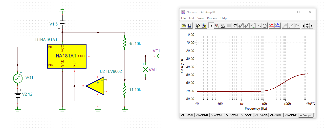
I notice that in the datasheet, the voltage applied toCis from a voltage follower as shown below. One additional operational amplifier is used and cost increases.

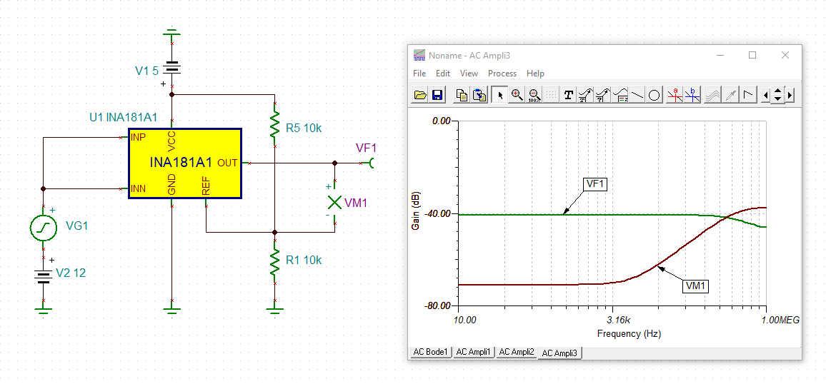
1) Can we just remove the operational amplifier and only use the divider resistors to get the reference voltage?  How much will it influence our output accuracy?

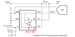
2) Or similarly as the application notes in INA199,  can we send the REF to the ADC port to reduce the influence of REF input impedance? (figure below)Do you think this method is also OK in INA181?

  • Hi Hazel,

    Or similarly as the application notes in INA199,  can we send the REF to the ADC port to reduce the influence of REF input impedance?

    With ideal amplifiers this would perfectly work. But with the real INA181 or INA199 some degradation can be seen, especially at high frequencies.

    This would be the common mode rejection of INA181-A1 with zero impedance +2.5V pseudoground:

    And this is the common mode rejection with a 10k voltage divider as pseudoground generation:

    hazel_ina181.TSC

    As you can see the common mode rejection is degraded at the high frequencies by about 10dB when using the ADC method. Without using the ADC method the common mode rejection is totally ruined and worse than 40dB.

    So, the ADC method can help to minimze the impact on the common mode rejection but cannot prevent the degradation totally.

    I wouldn't do that. It's so easy to add a buffer OPAmp behind the voltage divider that I wouldn't want to accept the 10dB loss of common mode rejection. Keep in mind, though, that the OPAmp must be able to provide a sufficiently low output impedance at high frequencies. So I would use a 1MHz OPAmp, nothing slower:


    hazel_ina181_1.TSC

    Kai

  • Hazel,

    The issue here is that to minimize the degradation to CMRR, accuracy etc., the system present at the REF node needs to be as low impedance as possible. We actually have data for what Kai demonstrates via simulation here. Please reference this app note, and check out table 6-1 on page 14 of the note. You can see that in the data, the error increases as the resistors used to set the reference increase, and most customers like to use large resistors to protect their power budget. This is not the case without buffering the impedance from the node. 

  • Hi  Kai,

    if my customer use low side shunt resistor to measure the DC motor current, do you think  can they use the resistor divider as the INA181's VREF ?

  • Hi Hazel,

    with 1k resistors and the 470n cap connected the degradation of common mode rejection is less worse than with 10k resistors and may be acceptable in your application now:

    Kai

  • Hazel, 

    The customer needs to run through the document I attached and perform their own assessment. Kai has even provided a model here that the customer can use to examine typical performance here that might help streamline their investigation. 

    The bottom line here though is that you are asking questions that the customer has to answer. I have no idea of their error budgets, power budgets, accuracy needs, etc.. This questions you are asking are not questions with an objective answer, but questions that are going to be based on their spec and the individual needs of the system. Only the customer can make that determination.