This thread has been locked.

If you have a related question, please click the "Ask a related question" button in the top right corner. The newly created question will be automatically linked to this question.

INA240: input bias current

Part Number: INA240

Hi,

There are a couple of questions about below simulation.

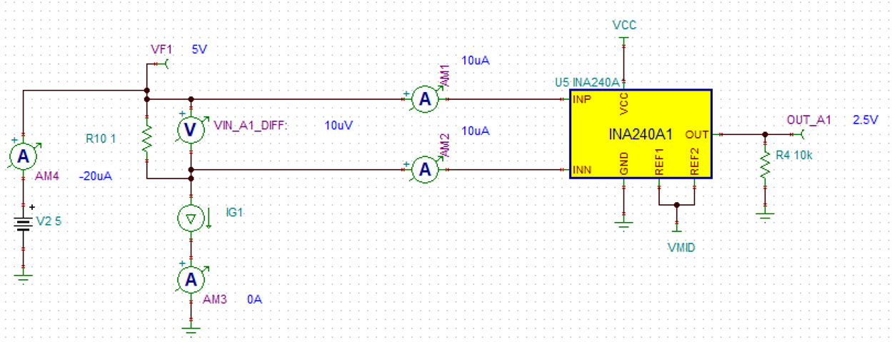
1. How can calculate input impedance of INP and INN?

current is 10uA@5V, 85uA@10V, 105uA@20V 

2. In the datasheet, typical input bias is 90uA. When there is forced current source from shunt resistor to ground, if current is limited below 90uA, is INA240 output abnormal?

  • Hi David,

    keep in mind that the figures of datasheet show a highly simplified internal circuit of INA240. The INA240 is far away from being a simple differential amplifier with simple input resistances. Don't overlook the "Bias" box in figure 9-1 which is also called "PWM rejection" in section 8-2. This box is mainly responsible for the input bias currents of INA240. Also see figure 7-14 of datasheet.

    Kai

  • Hi David,

    1 For common mode impedance – (20V-10V) / (105uA-85uA) =500kOhm.

    2 For the specific configuration in your schematic, the input bias current is supplied by V2. So there is no output problem. There are situations where the input could be starved and as a result the output becomes unpredictable. Here is what the output could look like when there is no DC return path for input bias current:

    More discussion can be found in section 5 of this app note.

    Regards, Guang