This thread has been locked.

If you have a related question, please click the "Ask a related question" button in the top right corner. The newly created question will be automatically linked to this question.

OPA656: Why does the working temperature rise to around 50C?

Part Number: OPA656
Other Parts Discussed in Thread: OPA657,

Hi 

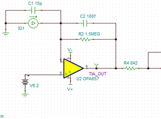
I'm testing a tanspidence circuit and find that the temperature at the case of OPA657/OPA656  rises to around 51~52C.

The ambient temperature is around 25C.

The OPAmp is supplied by ±4.5V,  the positive ref voltage is 2V, the output is around 1.5V and the ripple is about 37mVpp so I don't thing it gets saturated or oscilating.

And it keeps almost the same hot whenever the photo diode is connnected.

The datasheet shows it should have a very low power consumption.

It would be appreciated if anyone can help/explain it , thanks!

  • SOIC or SOT-23?

    The supply current of 14 mA will result in a noticeable temperature increase, but not that much.

    What is the load, i.e., how much current flows through R4?

  • Hi Follin,

    you are exceeding the maximum positive input voltage range. See section 7.5 of datasheet.

    Kai

  • Hi Kai,

    Yes thanks it's cloesd to common input's minimumu range but I tried 1.2V and it' still around 50C.

  • SOT-23, will try to measure the current (based on the simulation/calculation it shall not be too large.)

  • Hi Follin,

    the heat dissipation of OPA657 due to the quiescent current is up to 16mA x 4.5V x 2 = 144mW. Times the 150°C/W junction to ambient thermal resistance gives a temperature rise of 22K over the ambient temperature. With 25°C ambient temperature the case will heat up to 47°C. Isn't this exactly what you observe?

    Can you show your layout?

    The OPAmp is supplied by ±4.5V,  the positive ref voltage is 2V, the output is around 1.5V and the ripple is about 37mVpp so I don't thing it gets saturated or oscilating.

    Hhm, why is the output voltage arround 1.5V when the voltage at the +input is 2V? Without connected photodiode the voltages should be almost identical.

    Kai

  • Hi Kai, thanks for your reply again. As I understand, the θja is the resistance from juntion to ambient, so the junction heat up to around 47C as you calculated. The layout is very simple and there's no copper for heat dissipating(try to avoid any leakage current). So do you mean the heat dissipation from PCBA is very limited so the case temperature is almost the same as the junction? Anyway, compared with max junction temperature I think it's safe but if this is the reason and expanding the copper (Is only GND expanding engouh?) may help then I plan to optimize it in the next version.

    The output around 1.5V is with the photodiode connected.

  • Hi Follin,

    in opposition to through hole components SMD packages get their cooling from the PCB. So you should add some more copper to the pins of SOT-23 package.

    The output around 1.5V is with the photodiode connected.

    Ok.

    Kai